From transformers and switchgear to ring main units, substations, circuit breakers and smart components, Jubang provides integrated product support for power distribution projects.
Discover Jubang’s strengths in technology R&D, quality testing and smart manufacturing, supporting reliable electrical equipment and efficient power distribution solutions for global customers.
From technical consultation and OEM/ODM customization to EPC support, smart O&M, delivery documentation and after-sales service, Jubang supports your project at every stage.
Explore Jubang Group’s development history, intelligent manufacturing base, R&D platforms, CNAS-accredited laboratory and global project service capabilities.
Substation Auxiliary Power Systems: AC, DC and Backup Loads Explained
Release Time: 2026-07-25
Substation auxiliary power systems are the low-voltage AC and DC supplies that feed the station’s own equipment: protection, control, communications, transformer cooling, heating, lighting and safety loads. The primary circuits move energy to customers, while the auxiliary systems keep the substation itself observable, controllable and safe. Design guidance such as IEC 61936-1 treats batteries and the associated protection, control and auxiliary systems as part of the installation itself, not as an afterthought.
Before any supplier can quote a substation package, someone has to answer three questions: which loads exist, which of them must survive a loss of AC supply, and for how long. This guide walks through that reasoning and ends with the RFQ inputs a supplier needs.
Part 1. What do substation auxiliary power systems actually supply?
Start with a load inventory rather than a system diagram. Every substation consumes energy for its own operation, and each of those consumers is an auxiliary load: protection relays, breaker mechanisms, control and interlocking circuits, SCADA and communications equipment, transformer cooling fans and pumps, tap-changer drives, anti-condensation heaters, ventilation, lighting and socket outlets.
Two supply systems serve that inventory. The AC auxiliary supply carries the larger continuous and thermal loads, and the DC auxiliary system carries the loads that must never be interrupted. Technical references on station DC supply put it plainly: when the AC source sags or is lost, the DC system must still trip and close breakers, power protection and control, and keep communications alive long enough to bring the network to a safe state.
For readers building broader context on the equipment itself, the overview of substation equipment covers the primary apparatus that these auxiliary systems serve.
Part 2. How is the AC auxiliary system arranged?
The AC side normally begins at one or more station transformers or local network connections, runs through a main distribution board, and splits into feeders for cooling, heating, lighting and general station services. Its arrangement is a reliability decision before it is an electrical one.
Ask the project team to settle the following points early:
How many independent AC sources exist, and which owner rule sets that number.
Whether a transfer scheme between sources is manual or automatic, and who operates it.
Which feeders are essential (must return quickly after an outage) and which are non-essential.
Where the auxiliary distribution board sits and how it is accessed for maintenance.
How the AC system is protected and monitored, so a quiet failure does not go unnoticed.
A single station transformer can be acceptable for one project and unacceptable for the next. Duplication practice differs between owners, which is why the reliability requirement belongs in writing before the enclosure or board is chosen.
Part 3. What makes the DC auxiliary system different?
Unlike the AC side, the DC auxiliary system is built around stored energy. Its core is a battery, a battery charger and a DC distribution board with monitoring, as described in the reference material on substation DC auxiliary supply. A station can operate one DC system or several, and owners with higher availability requirements duplicate the battery and charger sets and connect the sections through a bus tie that stays open in normal service.
Why so much care for a small system? Because a failed DC supply can silently remove the station’s ability to detect faults, trip breakers and report its own state, a failure chain spelled out in the analysis of the auxiliary DC power system. Earth-fault detection, voltage supervision and charger alarms exist precisely because the DC system fails quietly rather than loudly.
Practitioner discussions also show that DC voltage levels and battery arrangements vary widely between utilities and plants. Treat the DC nominal voltage, the number of systems and the supervision scheme as owner decisions to confirm, not as catalog defaults.
Part 4. Which loads belong on which supply?
Allocate each load deliberately, because the allocation defines what survives an AC outage. Segregation between essential and non-essential feeders also decides how quickly staff can restore comfort loads without touching protection circuits.
Load group
Typical supply
Reasoning to record
Protection relays, trip coil and close coil circuits
DC, battery-backed
Must operate during the exact moment AC is disturbed
SCADA, RTU and communications equipment
DC, battery-backed
The network operator must see and command the station during outages
Emergency lighting and safety systems
DC or dedicated backup per owner rule
People may need to work in the station during a blackout
Transformer cooling fans, pumps and tap-changer drives
AC, essential feeder
Large motors are impractical on batteries; loss tolerated briefly with load limits per OEM guidance
Anti-condensation heaters, ventilation, general lighting, sockets
AC, non-essential feeder
Comfort and condition loads that can wait for supply restoration
Do not copy this table into a specification as-is. It is a starting point for the project’s own load inventory, and the owner’s operating philosophy, the OEM manuals and the applicable standards decide the final allocation.
Part 5. How do batteries and chargers keep backup loads alive?
In normal service the battery charger is the real DC source: it carries the continuous DC load and keeps the battery on float charge. The battery discharges only when the charger or its AC feed is lost, or when a momentary load such as a breaker operation exceeds the charger’s capability. That division of labour is why charger supervision matters as much as battery condition.
Battery capacity is not guessed. Recognized sizing practice, summarized well in the Battery Design overview of the lead-acid sizing method, works from a defined duty cycle: the sequence of continuous, intermittent and momentary loads the battery must carry for the required backup time, with corrections for temperature, ageing and design margin so voltage never falls below what the connected equipment tolerates.
Three inputs therefore come from the project, not from any article: the load inventory with durations, the required backup time set by the owner, and the minimum voltage windows of the connected equipment. Battery technology choice, cell count and capacity follow from those inputs in the responsible engineer’s calculation.
Part 6. How should auxiliary power be planned in a prefabricated substation?
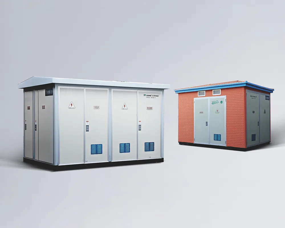
In a compact or prefabricated substation, the auxiliary systems share one documented enclosure with the primary equipment. The product standard for such assemblies, IEC 62271-202, frames them as enclosed assemblies with defined service conditions and rated characteristics, which means auxiliary circuits, heaters, lighting and monitoring are part of the configuration the supplier documents rather than a site improvisation.
That integration changes the buyer’s job in three ways:
The load inventory must be agreed before the enclosure is fixed, because space, heat and cable entries for auxiliary equipment compete with the primary circuits.
Battery location and ventilation, where a battery is included, become enclosure design questions with maintenance-access consequences, alongside the layout topics covered in the guide to prefabricated substation layout.
Auxiliary supervision signals should land in the same monitoring scope as the primary equipment, so the station reports charger trouble as readily as a breaker trip.
Compact stations are attractive partly because this engineering arrives pre-coordinated, a theme explored in the article on the advantages of medium voltage substations. The coordination is only real, however, when the quoted configuration documents it.
Fit boundary: this guide helps a buyer scope auxiliary AC and DC systems and prepare an RFQ. It does not select a DC voltage, size a battery or charger, set autonomy times or define acceptance values; those are project- and OEM-controlled decisions that need a load study and the owner’s reliability requirement. Confirm the load inventory, the reliability requirement and the equipment voltage windows before fixing any arrangement.
Part 7. Which JUBANG starting point fits an auxiliary power review?
For a substation package in which auxiliary circuits, monitoring and the enclosure are engineered together, begin with the YB-12 Intelligent Integrated Substation family from the prefabricated substations category. Where the priority is station-level supervision and data, the intelligent electrical system solution shows how JUBANG approaches monitoring integration. Both are family starting points: suitability, ratings and the auxiliary configuration of any quoted assembly must come from current JUBANG documentation and project review.
Send these RFQ inputs through Online Message so the review starts with substance:
Auxiliary load inventory with duty type (continuous, intermittent, momentary) and criticality.
Available AC sources, the expected transfer scheme and the owner’s reliability requirement.
Required backup time for protection, control, communications and emergency lighting.
Supply-voltage windows of the relays, coils, motors and heaters already selected.
Enclosure and climate context, including heating and cooling expectations.
Monitoring and alarm scope for both AC and DC auxiliary systems.
Documents expected with the quotation: drawings, configuration record, test records.
Quantity, delivery location and commercial delivery terms.
For anything that does not fit a form, raise it with the engineering team through Contact Us.
FAQ
What counts as an auxiliary load in a substation?
Anything the station consumes for its own operation: protection relays, breaker mechanisms, control circuits, SCADA and communications, transformer cooling, tap-changer drives, heaters, ventilation, lighting and safety equipment. The load inventory should name every item with its duty type.
Why do substations use both AC and DC auxiliary systems?
The AC system carries larger continuous and thermal loads economically, while the DC system provides stored energy for the loads that must ride through an AC disturbance. Removing either one leaves the station either unserviceable or unprotected.
Which loads should stay on the battery-backed DC system?
Loads whose failure would prevent fault detection, tripping, closing, indication or operator visibility: protection, trip and close circuits, SCADA and communications, plus emergency loads the owner assigns to DC. The allocation is recorded per project, not assumed.
How is the size of a substation battery decided?
The responsible engineer builds a duty cycle from the load inventory and required backup time, then applies recognized sizing practice with temperature, ageing and design-margin corrections so voltage stays above the equipment minimum. No generic capacity value substitutes for that calculation.
Can one auxiliary transformer supply the whole station?
Sometimes. The owner’s reliability requirement decides whether a second source, a transfer scheme or duplicated DC systems are required, and practice differs widely between utilities and industrial plants. State the requirement in the RFQ instead of assuming a default.
How does auxiliary power work in a prefabricated substation?
Auxiliary circuits, heaters, lighting and monitoring form part of the documented assembly configuration, engineered together with the primary equipment inside one enclosure. The supplier’s configuration documents, not the product family name, establish what a specific unit includes.
What auxiliary power information belongs in an RFQ?
The load inventory with duty types, AC source and transfer expectations, required backup time, equipment voltage windows, monitoring scope, expected documentation, quantity and delivery terms. With those inputs a supplier can propose an arrangement worth reviewing.
Products are exported to more than 100 countries and regions such as Africa, the Middle East, and the United Kingdom and Europe. It is a leading manufacturer of power distribution equipment in China.

 JUBANG