JUBANG



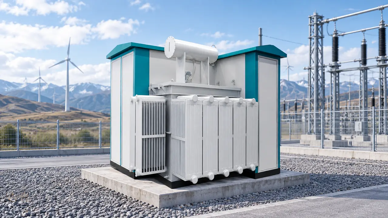
When Li Wei, a wind-farm commissioning manager in Hami, Xinjiang, encountered feeder trips after energizing a new collector string, he asked the supplier to investigate the transformer. The visible failure was rapid: 35 kV protection operated during turbine ramp-up, leaving several machines unavailable. Reviewing cable lengths, fault level, impedance, relay settings, and the energization sequence reversed the diagnosis. The equipment data had never been converted into a coordinated collector-node design.
Summary: A ZGS wind power integrated transformer substation must be specified as a complete turbine-to-collector interface, not accepted on a “35 kV” nameplate alone. The inquiry should state rated voltage and highest voltage for equipment, insulation levels, fault and harmonic inputs, switching-transient responsibilities, and four separate cold-duty conditions. Freeze the single-line diagram, studies, and minimum evidence package before release for manufacture.
A typical package combines a turbine step-up transformer, MV switching or protection, LV terminations, auxiliaries, monitoring interfaces, and an enclosure. Many utility-scale turbines use output around 690 V before step-up, but the turbine supplier’s confirmed voltage, converter behavior, and operating envelope must govern the design. Integration can reduce field interfaces; it also concentrates responsibility at one collection node.
Does a 35 kV nameplate define a complete collector node?
No. The transformer ratio identifies nominal winding voltages, but it does not define highest voltage for equipment, frequency, neutral earthing, insulation withstand levels, clearances, short-time withstand duty, switching, or protection. A 35 kV collector description may require equipment at a higher standardized rated voltage under the applicable network practice. State both the transformer ratio and required equipment rating.
Nameplate-to-node rule: record rated/maximum voltage, power-frequency and lightning-impulse withstand levels, creepage or external-clearance assumptions, rated current, short-time withstand current and duration, making duty, and internal-arc requirements where applicable. IEC 60076-1 provides the general transformer framework, IEC 60076-3 addresses insulation levels and dielectric tests, and IEC 62271-202 covers prefabricated high-voltage/low-voltage substations. None of those references substitutes for project values in the datasheet.
How should impedance, fault level, and protection inputs be specified?
Transformer short-circuit impedance affects through-fault current and voltage drop, so it is both an equipment parameter and a network-study input. State the guaranteed value and tolerance at the agreed rating and tap. Then provide maximum and minimum source fault levels, collector topology, cable impedances, neutral-earthing arrangement, turbine-converter fault contribution versus time, and required clearing times. Converter controls can limit or shape current differently from a synchronous source; a relay engineer needs the manufacturer’s validated current and sequence data, not only a headline short-circuit ratio.
An illustrative screen shows the dependency. For a 3.6 MVA, 35 kV unit with 8% impedance, rated current is about 59 A and the transformer-only symmetrical current would be about 738 A if upstream and cable impedances were neglected. This is not a breaker-selection calculation. The project fault study should use the applicable IEC 60909 method or the grid operator’s required method and include real source, cable, earthing, and converter models.
The protection schedule should assign relay functions and settings, CT/VT ratios and classes, trip circuits, interlocks, remote commands, records, and time synchronization. Phase/earth overcurrent, transformer indications, temperature functions, and differential or restricted-earth-fault protection where selected must coordinate with turbine controls and upstream devices. Equipment ratings alone cannot demonstrate selectivity.
What loading and harmonic data make the thermal design credible?
Wind duty is variable: calm periods, rapid ramps, sustained high output, reactive-power operation, and curtailment create repeated heating and cooling rather than one constant load. This thermal cycling affects insulation, seals, connections, and cooling components over time. IEC 60076-7 provides loading guidance, but a thermal assessment still needs the project’s ambient profile, load-duration curve, reactive-power range, cooling mode, and any overload or curtailed operating states.
Harmonic current can increase winding eddy and structural stray losses. A procurement phrase such as “low THD” is insufficient because different harmonic orders produce different loss effects. Require the turbine or converter supplier’s expected current spectrum at relevant active and reactive operating points, the calculation method, and the party responsible for confirming hot-spot and loss performance. Compare transformer loss guarantees at the same rating, reference temperature, tap, and waveform assumptions.
| Collector-node input | Why the 35 kV label is insufficient | Required project evidence |
|---|---|---|
| Voltage and insulation | Nominal voltage does not define highest equipment voltage, withstand levels, or clearances. | Approved single-line diagram, insulation schedule, and datasheets. |
| Fault and protection duty | A transformer impedance value omits source, cable, earthing, and converter behavior. | Maximum/minimum fault study, relay philosophy, CT/VT schedule, and settings ownership. |
| Thermal and harmonic duty | Transformer MVA alone omits cycling, reactive power, ambient conditions, and harmonic losses. | Load-duration profile, harmonic spectrum, derating curves, and guaranteed loss data. |
| Mechanical and site duty | An enclosure drawing does not prove route, lifting, foundation, or maintenance suitability. | Transport envelope, mass and center of gravity, lifting plan, foundation loads, and clearances. |
Will insulation coordination cover cables, arresters, and switching transients?
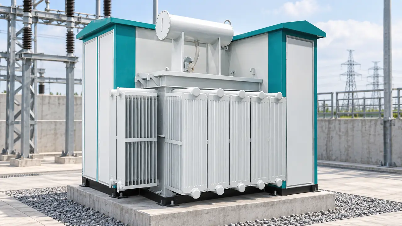
Collector cables, switching devices, arresters, transformer terminals, and grounding form one transient system. Long cable sections can change wave behavior; energization, interruption, restrike, lightning, and grounding configuration can all affect terminal stress. A transformer dielectric test report therefore proves the unit met a defined test duty, not that the installed collector node is coordinated under every site event.
Who owns the switching study and arrester-to-cable interface?
The contract should identify the switching device type, cable construction and length, transformer terminal arrangement, arrester technology and protective level, arrester location and lead length, cable-screen bonding, and the network grounding model. It should also name the party that performs the insulation-coordination or electromagnetic-transient study, supplies models, accepts assumptions, and resolves a mismatch. Surge arresters should be selected and located from that coordinated study; “arrester included” is not a complete performance requirement.
Earthing responsibility needs the same clarity. Bond the transformer tank, switchgear earth bar, cable screens, enclosure steel, doors, and accessible metalwork into the site system. Step and touch voltage depend on soil resistivity, fault current, clearing time, grid geometry, and transferred potentials; a single low-resistance target does not demonstrate safety. IEC 61400-24 is relevant to the lightning-protection interface for wind installations, while the destination market’s electrical-safety rules govern the final installed system.
Specify the enclosure and internal arrangement alongside these interfaces. IEC 62271-202 addresses prefabricated substations, and IEC 60529 defines IP-code tests. An IP rating does not by itself demonstrate corrosion resistance, condensation control, internal-arc performance, or suitability for salt, sand, icing, and ultraviolet exposure. Those service conditions and acceptance evidence belong in the inquiry.
Can the package survive storage, cold energization, and normal winter operation?
“Low-temperature suitable” hides at least four different duties: the minimum transport/storage temperature; de-energized survival without damage; cold energization from the site’s starting temperature; and continuous normal operation after auxiliary heat and load are available. Record a temperature for each duty and state any permitted preheating time. A design qualified for normal operation at one temperature may not be ready for immediate energization after an unheated winter shutdown.
Which winter auxiliaries and materials must be verified before award?
For cold energization, define the source and sequence for heaters, protection, controls, communications, breakers, and motor operators. Verify heater capacity and thermostat logic, station-service availability, control-battery or DC-supply performance, insulating-liquid viscosity and pour point, seal and gasket temperature capability, cable flexibility, lubricants, and condensation management. The oil supplier’s data and the transformer thermal design should support the stated start condition; do not treat a pour point as the transformer’s guaranteed operating limit.
Altitude is another project input rather than a universal product claim. Site elevation can affect air insulation and cooling, so confirm correction methods, external clearances, ventilation, and thermal capability for the actual elevation. Do not generalize a competitor’s advertised altitude, footprint, or rating to all ZGS packages. Transport shock, road gradients, shipping splits, and inspection after arrival should also be addressed for remote wind sites.
Which package architecture produces the lowest lifecycle risk?
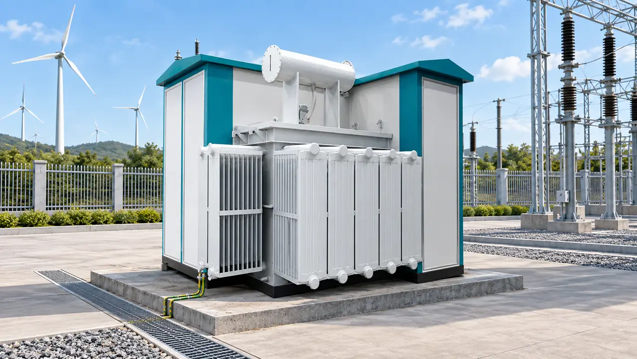
An integrated ZGS arrangement can reduce field assembly and consolidate wiring and interlocks, while separate transformer and switchgear packages can provide more layout freedom and component-level replacement options. Neither architecture is automatically lower cost. Compare civil works, road and crane constraints, terminations, commissioning labor, losses, spares, service access, outage value, and responsibility for interface defects.
| Decision dimension | Integrated ZGS package | Separate transformer and MV equipment |
|---|---|---|
| Interface control | One package supplier can coordinate wiring, interlocks, enclosure, and factory checks if the scope is explicit. | Buyer or EPC must manage boundaries among equipment suppliers. |
| Transport and installation | Fewer site interfaces, but mass, dimensions, route, crane capacity, and foundation tolerance can be limiting. | More site work, but shipment and layout can be divided. |
| Maintenance and replacement | Compact clearances and shared outage boundaries require careful review. | Individual assets may be easier to isolate, access, or replace. |
| Evidence and acceptance | Package-level FAT can test more interfaces when the agreed procedure includes them. | Individual FATs need a defined site integration and SAT plan. |
| Lifecycle cost | Can reduce field coordination cost; a package outage may affect the complete turbine node. | May fit projects with established local spares and multi-vendor service resources. |
Use the wind farm’s operating profile to value losses and unavailable energy; do not multiply nameplate loss by generic annual hours. An illustrative TCO model should state energy price, utilization, discount period, outage probability, repair time, mobilization cost, and residual assumptions. Test sensitivities because access and outage consequences vary by site.
What evidence should be contract deliverables before shipment?
Start selection by freezing turbine rating and voltage, collector topology, earthing method, site conditions, and the approved single-line diagram. In search and tender language, a 35kV wind turbine combined transformer still needs that project definition. Request the 40.5 kV metal-clad switchgear configuration or other MV arrangement only after its voltage, insulation, short-circuit duty, access, and protection role are confirmed. A product link is not evidence of project compliance.
Minimum evidence package: turbine converter electrical and fault-current data; load and harmonic profiles; collector-cable data; maximum and minimum fault levels; transformer impedance, loss, thermal, and derating data; relay, CT, and VT responsibility; insulation-coordination assumptions; cold-start sequence; auxiliary-load schedule; transport, lifting, and foundation plan; approved drawings; FAT and SAT scope; spare-parts list; winter spares; and a settings/firmware baseline where intelligent devices are supplied. Each item should have a named originator, reviewer, due date, and acceptance criterion.
FAT scope should distinguish routine transformer tests, switchgear checks, wiring/interlock verification, protection injection where included, auxiliary changeover, SCADA point checks, and enclosure inspection. SAT should address post-transport assembly, cable tests and phasing, earthing continuity, settings, functional trips, communications, energization hold points, and the agreed cold-start demonstration. IEC references are requirements or test frameworks, not blanket product certifications. State editions, deviations, reports, witnesses, and destination-market obligations.
Jubang Group can support buyers evaluating a ZGS wind power integrated transformer substation by aligning configurable equipment information, requested tests, and documentation with an approved project datasheet. Buyers comparing a broader ZGS combined transformer range should still evaluate each proposed configuration against the same collector-node evidence.
Which questions should buyers resolve before award?
What is a ZGS Wind Power Integrated Transformer Substation?
It is a packaged wind-farm collection-node solution that combines a step-up transformer with MV switching or protection interfaces, low-voltage connections, auxiliaries, and an enclosure. The exact boundary varies, so the supplier’s scope and the EPC’s cable, grounding, controls, and protection responsibilities must be written into the interface schedule.
What voltage do wind turbines use before grid connection?
Many utility-scale turbines generate at low voltage, commonly around 690 V, before local step-up to a medium-voltage collector network such as 35 kV. Turbine designs vary; use the manufacturer’s confirmed voltage, frequency, converter, reactive-power, and fault-current data for the project specification.
Why are combined transformers used in wind farms?
They consolidate transformation, switching, protection interfaces, and auxiliaries near the turbine, potentially reducing field connections and interface ambiguity. The value depends on transport access, factory-test scope, maintenance clearances, outage strategy, and whether the package has been coordinated with the collector-network studies.
How do low temperatures affect wind power transformers?
Low temperatures can affect insulating-liquid viscosity, seals, batteries, heaters, mechanisms, control electronics, and flexible cables. Specify transport/storage, de-energized survival, cold energization, and normal operation separately, then verify the required auxiliary power and start sequence.
What protection equipment is integrated in a wind farm substation?
Depending on the design, the package may include MV breakers or switches, protection relays, CTs, VTs, surge arresters, transformer temperature or pressure indications, trip circuits, and remote-control interfaces. The list does not replace a study: ratios, classes, settings, and trip logic must coordinate with the turbine and upstream network.
How do you select a wind turbine step-up transformer?
Begin with turbine rating and voltages, then verify impedance, vector group, tap range, losses, insulation levels, cooling, harmonics, earthing, environmental duty, and transport constraints against the approved studies. Compare bids on guaranteed values, interfaces, test evidence, and lifecycle consequences rather than nominal MVA and 35 kV wording alone.
Which official standards should buyers verify?
- IEC 60076-1: Power transformers—General
- IEC 60076-3: Insulation levels, dielectric tests and external clearances in air
- IEC 60076-7: Loading guide for mineral-oil-immersed power transformers
- IEC 62271-202: High-voltage/low-voltage prefabricated substations
- IEC 61400-24: Wind energy generation systems—Lightning protection
Collector-node discipline turns an integrated package from a collection of nameplates into a verifiable turbine-to-grid interface. When the project reaches equipment selection, contact Jubang Group to discuss the approved network data, environmental duty, delivery constraints, and evidence required for a suitable 35 kV ZGS solution.