JUBANG



When an electrical lead named Farid near Sabang on Pulau Weh, Indonesia, encountered unstable voltage, he increased the battery converter rating and restarted. A refrigeration compressor started; within minutes, frequency collapsed and the feeder tripped. Event review reversed the diagnosis: kilowatts were sufficient, but grid-forming control, transformer inrush, protection, and the black-start boundary had never been specified as one system. The problem was selection and interface definition, not a defective product.
Summary: An Off-grid American energy storage converter booster for remote area projects must establish voltage and frequency, raise converter output to medium voltage, isolate faults, and restore essential loads without a dependable utility grid. For an illustrative 1.5 MVA unit, current falls from about 1,255 A at 690 V to 79 A at 11 kV, yet voltage transformation alone does not resolve inrush or protection coordination. Freeze control ownership, the staged restoration sequence, common-failure boundaries, remote spares, and FAT/SAT evidence before ordering.
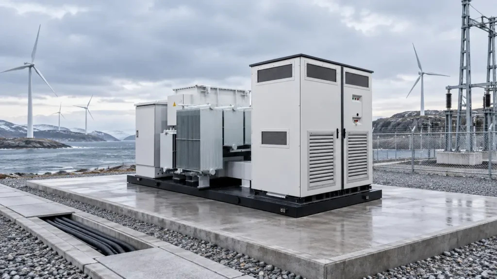
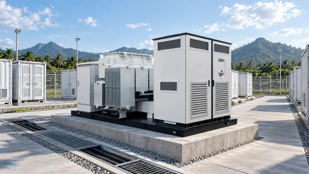
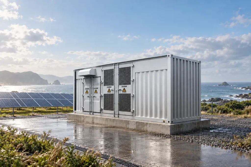
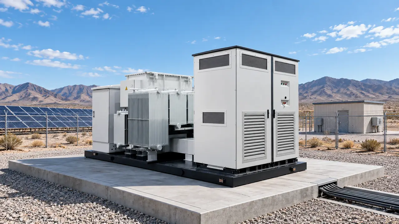
A Packaged energy storage converter booster (American style) combines the power conversion system (PCS), a step-up transformer, medium-voltage switching, and protection in an outdoor package. “American style” describes a compact combined-transformer arrangement; it does not by itself demonstrate approval for North America or any destination market.
Which source will establish the waveform in every operating mode?
A grid-following PCS measures an existing voltage waveform and injects controlled current into it. A grid-forming PCS creates the voltage and frequency reference when the utility or diesel bus is absent. That is a control responsibility, not a marketing label: the operating-mode matrix must identify who forms the reference during normal islanding, black start, generator parallel operation, transitions, and degraded communications.
Real-power rating does not answer this question. MVA capability, reactive-current limits, overload magnitude and duration, state-of-charge reserve, and control response determine whether the system can hold voltage through a motor start or load step. Specify the largest credible step, permissible frequency nadir, recovery time, fault-current contribution, harmonic limits, and the conditions for load shedding. The IEC 62933 series provides a framework for electrical energy storage systems, but the project still needs a functional specification and configuration-specific tests.
Assign each interface to one accountable party before design freeze
The responsibility schedule should name who supplies the PCS control model, validates firmware, sets protection, confirms transformer data, selects MV switchgear, powers station service and HVAC, maps communications, designs grounding, and integrates battery limits. Otherwise, individually compliant components can leave an unowned function between them.
Consider a 400 kW motor that draws five times rated current during direct-on-line starting. A PCS capped near 1.1 per-unit current cannot behave like a synchronous generator. A variable-frequency drive, soft starter, smaller starting blocks, or revised restoration sequence may be needed; increasing continuous kW alone may not correct the problem.
How will the transformer be energized without collapsing the island?
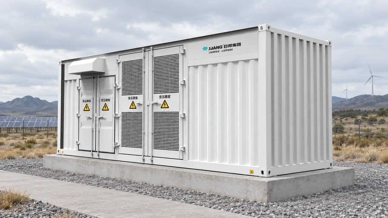
Transformer magnetizing inrush depends on switching angle, residual flux, core design, system impedance, and the voltage-forming source. It may be several times rated current briefly, so a continuous-current check is insufficient. State whether each mode energizes from the utility, diesel, PCS low-voltage side, or MV side, then model that source’s current ceiling.
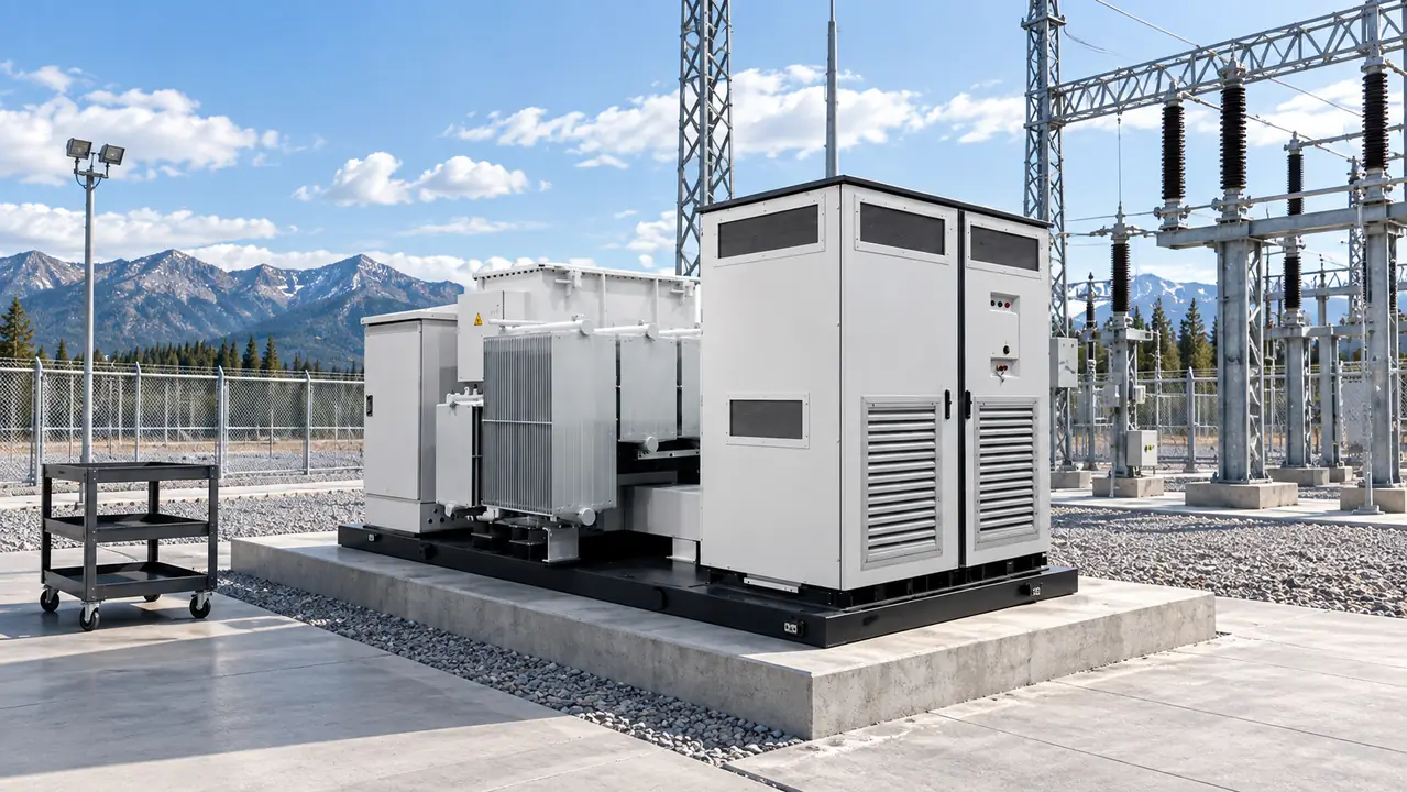
Request transformer impedance, vector group, taps, no-load and load losses, excitation data, insulation level, thermal limits, and converter-duty assumptions. IEC 60076-1 covers general power-transformer requirements; the purchase specification must still define project loading, harmonic content, ambient conditions, and energization duty. Where the PCS must magnetize a dead transformer, the study should test credible residual-flux and point-on-wave cases and demonstrate that converter protection will not trip.
Protection must distinguish inrush and permitted load steps from converter-limited faults. Coordinate applicable transformer differential, earth and phase overcurrent, voltage, frequency, temperature, pressure, DC supervision, and breaker-failure logic. Grounding changes earth-fault magnitude, so strong-grid settings are not an acceptable baseline.
A staged restoration plan should prove black start before procurement
Black start is a chain of available energy, control power, and permissions. First restore station service, including the battery controls, protection DC supply, HVAC essentials, and communications. Next start the reference-forming source and establish a stable low-voltage bus. Then energize the transformer and MV bus, close critical feeders in agreed blocks, and add non-critical loads only after voltage, frequency, thermal state, and state of charge are inside limits.
For each stage, record expected kW, kvar, transient current, duration, minimum state of charge, permissives, abort thresholds, and fallback action. Identify external UPSs, generators, manual switches, communications, and operator actions. If an external source must energize the transformer, the offer should not be represented as autonomous black start.
Planned islanding, unplanned source loss, resynchronization, communications failure, and a cold start after extended shutdown need separate test cases. A sequence that works with a warm transformer and full battery may fail after a long outage. The buyer should therefore require a witnessed demonstration of the contracted sequence, not only a PCS bench test or a generic statement that black start is supported.
Remove common failure points before calling the design redundant
Two PCS modules do not create end-to-end redundancy when they share one transformer, MV breaker, protection panel, control network, HVAC controller, auxiliary transformer, or DC supply. Build a common-point-of-failure register and ask, for each item, whether failure stops the entire site, whether it can be safely isolated, and how long replacement will take. Redundancy must follow the critical-load path, not the component count.
N+1 service is credible only if the remaining modules carry the critical load at site ambient conditions and the failed unit can be isolated without de-energizing the common bus. Also review maintenance bypasses, protection blind spots, shared sensors, network switches, hazard zones, and fleet-wide software changes.
Which package architecture best contains remote-site risk?
| Decision factor | Single integrated package | Modular PCS with common transformer | Distributed smaller boosters |
|---|---|---|---|
| Waveform control | Fewer interfaces, but one control failure domain | Requires validated power-sharing and mode-transfer logic | Supports zoned islands but needs coordinated references |
| Common failure point | Package shutdown may remove all capacity | Transformer, MV bus, and auxiliaries may remain common | Geographic separation reduces shared exposure but adds links |
| Protection evidence | Factory coordination can cover more of the assembly | Common-bus and converter fault models are essential | More relays, settings groups, and boundary tests |
| Site logistics | Fewest field joints; heaviest single lift | Moderate lifts and field interconnection | Small lifts; more foundations and cable routes |
| Service strategy | Concentrated access and spares | A PCS module may be serviced while others operate | Zone isolation is easier; travel between assets increases |
| TCO tendency | Favors sites with adequate transport and lifting access | Often suits phased capacity with a managed common risk | May justify added complexity where outage consequence is high |
Remote cost includes transport, customs, crane reach, road limits, foundations, terminations, commissioning, training, spares, and repeat travel—not only factory price. As an illustrative calculation, assume 1.5 MW dispatch for 8 hours per day on 330 days per year, with combined conversion and transformation loss reduced from 3.5% to 2.0%. Energy conserved would be 1.5 MW × 8 × 330 × 1.5% = 59.4 MWh per year. At an illustrative avoided cost of US$0.28/kWh, the annual benefit is US$16,632 before maintenance, degradation, and financing; buyers should replace every assumption with measured project data.
Remote readiness requires spares, firmware, and settings control
| Remote application | Primary design decision | Evidence to close before shipment | Site-readiness control |
|---|---|---|---|
| Island clinic and telecom hub | Critical-load continuity and salt exposure | Restoration test, corrosion specification, auxiliary-load schedule | Critical spares, remote support, and manual fallback |
| Desert construction camp | Heat, dust, and changing demand | Thermal derating curves, enclosure evidence, load-growth margin | Filters, fan assemblies, and inspection intervals |
| Mining or quarry microgrid | Motor starts, harmonics, and severe duty | Dynamic, harmonic, and protection-coordination studies | Replacement sensors, relay files, and start-sequence record |
| Remote utility feeder support | Source transitions and maintainability | Interface schedule, communications mapping, FAT/SAT plan | Approved firmware image, settings baseline, and rollback method |
Base spares on failure consequence, lead time, shelf life, and local replacement capability. Review fans, filters, control-power supplies, communications modules, sensors, breaker mechanisms, fuses, and a serviceable PCS module where applicable. Every part must match the installed revision.
At handover, archive approved PCS, battery, relay, PLC, HMI, and network firmware versions with available checksums; retain settings files, parameter reports, licenses, backups, change history, and a tested rollback procedure. Keep a controlled local copy. Later updates should trigger a controls, protection, communications, cybersecurity, and warranty review.
FAT and SAT must close different evidence gaps
Factory acceptance testing should verify what can be controlled before shipment: visual and dimensional checks, nameplates, wiring, insulation and continuity checks, transformer routine-test records, switchgear operations and interlocks, relay secondary injection, communications mapping, alarms, emergency stops, cooling sequences, auxiliary loads, and configured control modes. For a prefabricated assembly, require the exact tested configuration, report identifiers, deviations, and witness or hold points—not a certificate from a related model.
Where full-power testing is unavailable, state the limitation and agree how simulation, controller hardware-in-the-loop tests, component reports, and site tests will close the gap. FAT should capture the released software and settings baseline, signed punch list, single-line diagram, protection study, fault-contribution model, transformer impedance and loss data, thermal derating curves, auxiliary-load schedule, spare-parts list, and commissioning procedure.
Site acceptance testing should prove installation-dependent behavior: grounding continuity, phasing, cable and breaker checks, CT/VT polarity, trip paths, communications to the operating system, HVAC under actual auxiliaries, generator or utility transitions, controlled load steps, restoration stages, and shutdown response. Record initial conditions and calibrated measurements, then define pass/fail limits for voltage, frequency, time, alarms, and protection. A successful component FAT cannot substitute for an integrated SAT.
Standards define scope, while project evidence proves suitability
IEC 62271-202 addresses AC prefabricated substations, while IEC 62271-200 addresses metal-enclosed switchgear and IEC 62271-1 provides common specifications. IEC 60076-1 addresses power transformers. IEC 60529 classifies enclosure ingress protection, but an IP code alone does not establish corrosion resistance, solar-load performance, condensation control, or filter-maintenance intervals.
These standards contain scoped requirements and test methods; they are not interchangeable universal approvals. State the applicable edition, destination-market adoption, ratings, tested assembly variant, laboratory, and deviations. Local grid rules, fire requirements, environmental permits, transport law, and electrical codes may add obligations. Unsupported compliance language can lead to retesting, delayed energization, rejected equipment, and disputed warranty boundaries.
Use a contractual evidence package to make the final selection
- Issue an operating-mode matrix for grid-forming, generator-parallel, islanded, transition, emergency, degraded, and maintenance states.
- Provide load profiles, motor starts, fault levels, grounding, battery limits, climate, altitude, and acceptable recovery envelopes—not only MW and kV.
- Contract the single-line diagram, interface schedule, studies, model files, software versions, relay settings, FAT witness points, black-start demonstration, and SAT limits.
- Verify shipping dimensions and mass against the actual route, then reserve lifting, laydown, cable-bending, ventilation, and maintenance clearances.
- Compare offers on lowest delivered lifecycle cost, including common-failure exposure, outage consequence, spares, technician travel, and end-of-life work.
At this selection stage, Jubang Group can support an interface-led review of the GTE-ZGS American-style energy storage conversion and step-up unit, the ZGS combined transformer, and the YB-12 intelligent integrated substation. Buyers should request configuration-specific drawings, ratings, and test evidence; a family page is a starting point, not proof for a final assembly.
Buyers frequently ask these six specification questions
What is a Off-Grid American Energy Storage Converter Booster for Remote Areas?
It is a packaged system that converts battery DC power to controlled AC power, raises voltage through a transformer, and connects the output to a protected medium-voltage microgrid. For true off-grid duty, it must be specified for grid-forming control, auxiliary supply, islanding, and the agreed restoration sequence.
What are the main components of a substation?
Main components include transformers, busbars, switchgear, circuit breakers or load-break switches, instrument transformers, surge protection, grounding, relays, control power, and communications. In an energy-storage booster, the PCS, battery interface, HVAC, and station-service loads are also part of the functional chain.
What are the main types of substations?
Substations may be classified by function—step-up, step-down, switching, converter, or collector—or by construction, such as conventional outdoor, indoor metal-enclosed, prefabricated compact, and mobile. The appropriate type depends on voltage, fault duty, environment, expansion, transport, and maintenance strategy.
How do medium voltage substations distribute power safely?
They use insulation coordination, grounding, interlocks, switching devices, and protection relays to route power and isolate faults. Safety depends on calculated fault duty, verified ratings, coordinated settings, safe access, and commissioning tests, not on enclosure style alone.
What is the difference between a compact substation and a conventional substation?
A compact substation integrates transformer, medium-voltage, and low-voltage functions into a factory-built enclosure, reducing site interfaces and footprint. A conventional substation offers more layout flexibility and easier expansion, but it usually needs more civil work, field assembly, and interface testing.
How do you select substation equipment for a project?
Start with the single-line diagram, operating modes, voltage, load, fault duty, grounding, environment, and applicable utility rules. Then verify equipment ratings, transformer duty, protection, communications, transport limits, test evidence, spares, and lifecycle cost for the exact configuration.
Primary references buyers can use to verify the specification
- International Electrotechnical Commission, IEC 62271-202, High-voltage switchgear and controlgear—AC prefabricated substations.
- International Electrotechnical Commission, IEC 60076-1, Power transformers—General.
- International Electrotechnical Commission, IEC 62933 series, Electrical energy storage systems.
The dependable remote microgrid is the one whose operating boundaries were proved before the first truck left the factory. For a configuration review based on your single-line diagram, load steps, destination conditions, and delivery route, contact Jubang Group.