JUBANG



When Maria Lopez, an EPC commissioning lead in Phoenix, Arizona, closed the MV disconnect on a 2 MW battery block, the PCS tripped within seconds, a transformer alarm appeared, and the controller rejected restart. The team suspected a defective converter. Review reversed that diagnosis: transformer impedance, inrush duty, switchgear settings, grounding, and the 46 °C ambient case had never been assessed as one system. The equipment was serviceable; its selection and interfaces were not.
Summary: Buy an American Style Energy Storage Converter Booster as a coordinated electrical package, not as a PCS efficiency number attached to a transformer nameplate. Define continuous and overload kVA, the package-efficiency boundary, auxiliaries, transformer energization source, protection models, and interface owners before comparing bids. IEC 60076-1 applies to transformer requirements, IEC 62271-202 to prefabricated substations, and the applicable IEC 62933 documents to electrical energy storage systems; none replaces a project-specific protection and grounding study.
Define the package boundary before comparing efficiency
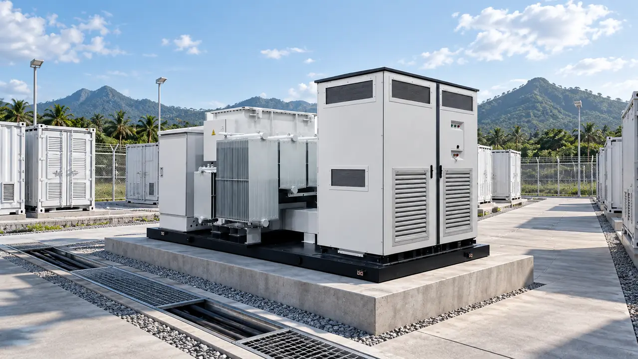
The PCS converts energy bidirectionally between the battery DC bus and the AC system; the transformer raises its LV output to the collector voltage. MV switching, protection, station service, cooling, communications, and grounding complete the package. “American PCS boost integrated box substation” generally describes a pad-mounted transformer and MV arrangement with a PCS on the same skid or nearby; it does not define a universal rating or test scope.
Efficiency boundary: a PCS conversion-efficiency value cannot be compared directly with a guarantee at the MV terminals. Package results may include transformer losses, reactors, cabling, HVAC, heaters, controls, and station service. Require meter locations, operating voltage, power factor, ambient, loading points, auxiliary treatment, measurement uncertainty, and whether each figure is tested, calculated, or a datasheet claim.
An illustrative boundary check shows why this matters. If 1,000 kW enters the PCS and 970 kW reaches the MV delivery point while cooling and controls draw 8 kW inside that boundary, the AC package efficiency is 97.0% if auxiliaries were already included in the measured input-to-output result. It is not valid to subtract the same 8 kW again. Conversely, a PCS-only efficiency measured at its AC terminals says nothing about transformer and auxiliary losses. Lock the commercial guarantee to a single-line diagram and a meter schedule.
Match PCS and transformer ratings to the real duty cycle
Separate continuous output, overload duration, and transformer MVA
Start with the PCS maximum apparent power, continuous active power, reactive range, overload magnitude and duration, switching frequency, harmonic spectrum, grid-forming capability, and temperature/altitude derating. Then select transformer MVA from the combined P–Q envelope and duty cycle rather than copying the PCS MW label. For example, a 1,250 kVA transformer carrying 1,000 kVA is at 80% of nameplate. As an illustrative approximation, its copper-loss component is 0.82, or 64%, of the full-load value; actual winding temperature and loss guarantees must come from supplier data and the specified reference conditions.
Specify LV/MV voltages, frequency, vector group, taps, impedance and tolerance, insulation, cooling, guaranteed losses, acoustic limits, and ambient profile. IEC 60076-1 provides general transformer requirements, but the purchase specification still needs exact service conditions and agreed tests. Keep MVA and impedance in the protection model because both affect fault level, voltage drop, and relay coordination.
Specify who energizes the transformer in every operating mode
Residual core flux, closing angle, source impedance, voltage, cables, and the switching point all affect inrush. Define three modes. For grid-connected start, state whether the utility energizes from the MV side or the PCS closes onto an energized transformer. For a weak grid, assess voltage depression, harmonics, relay security, and any need for controlled switching, pre-insertion impedance, or a revised sequence. These are project options, not default features.
In black start, a grid-forming PCS may face magnetizing demand before establishing a stable MV bus. Its current limiting differs from a strong utility source, so use validated PCS dynamic and fault models, transformer magnetizing data, and the actual cable network. Establish station service, controls, and communications; enable the reference-forming source; energize the transformer and MV bus; pick up critical loads; then add non-critical loads. FAT simulations and site tests should confirm the sequence.
Choose the American or European arrangement from site constraints
| Decision dimension | American-style package | European-style package | Evidence needed |
|---|---|---|---|
| Primary layout | Pad-mounted transformer and MV switching often use one guarded tank or closely integrated arrangement | MV gear, transformer, and LV/PCS functions are commonly divided into coordinated compartments | Single-line, general arrangement, utility access rules |
| Isolation and service | Compact pad with controlled access to cable and switching areas | Compartment access can support separate maintenance boundaries | Isolation steps, replacement route, lockout points |
| Thermal path | Heat leaves through the tank, radiators, and any package ventilation | Airflow may be separated by functional zone | Loss schedule, thermal model, derating curves |
| Protection options | Fuses, load-break switches, or project-specific relaying may be integrated around the pad | Breaker, relay, and ring-main arrangements can be configured by compartment | Fault model, time-current study, utility approval |
| Lifecycle tradeoff | Familiar pad interfaces may reduce civil and field-wiring work | Compartmentalization may simplify testing or component access | Delivered scope, spares, losses, labor, outage plan |
Neither layout is inherently better. Compare identical functions, test boundaries, environmental duty, access, and owner-supplied items. Select from utility isolation practice, footprint, fault level, transport, fire strategy, and replacement plan.
Treat grounding, enclosure, and cooling as one safety design
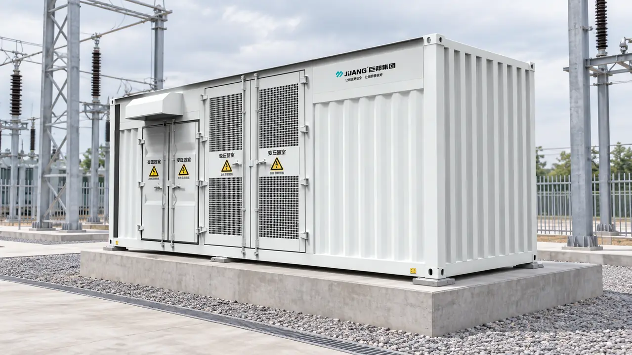
Define transformer neutral treatment, PCS DC isolation, cable-screen and enclosure bonding, electrode connections, touch and step criteria, and clearing time. Grid resistance alone does not establish safety; soil resistivity, geometry, transferred potential, fault current, and clearing time interact. Show bonding points on the general arrangement and single-line, then verify continuity and site grounding during SAT.
IEC 60529 defines ingress-protection tests, not resistance to UV, salt, sand, condensation, flooding, or corrosion. Specify IP by compartment with gaskets, drains, pressure relief, heaters, coatings, filters, and access. For oil-filled equipment, define containment, relief, fire separation, and oil-handling access; “outdoor” proves none of these features.
Thermal verification begins with a traceable loss schedule. Illustratively, 20 kW of PCS loss plus 12 kW of transformer loss creates 32 kW of internal heat before solar gain and auxiliaries are considered. The supplier should show the calculation boundary, airflow or radiator assumptions, alarm and fan logic, dirty-filter case, and temperature/altitude derating curves. Confirm that modeled clearances remain available after real cable bends, barriers, and service platforms are installed.
Make installation speed conditional on field-ready interfaces
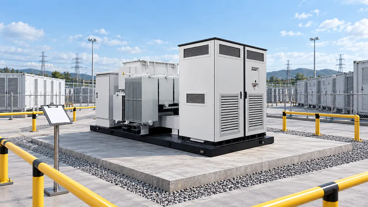
Factory assembly can reduce site wiring, but a skid is not automatically plug-and-play. Schedule advantage depends on transport limits, lifting points, foundation and anchor tolerances, trench alignment, termination space, containment, fire clearances, and approved drawings. Delivery before the pad or relay settings are ready moves work rather than removing it.
Define which interlocks, I/O, communications, alarms, relay logic, fans, and emergency stops FAT will demonstrate with simulated external equipment. SAT must close insulation, phasing, grounding continuity, cable tests, agreed injection, settings, communications, and energization. Assign responsibility for test sources, temporary power, network access, witnesses, and corrections.
Total cost should follow the operating profile. Illustrative only: reducing continuous no-load loss by 1.5 kW avoids 13,140 kWh per year (1.5 × 8,760). If load loss is 4 kW lower and the relevant winding operates at 60% average per-unit load, the simple squared-load estimate is about 12,614 kWh per year (4 × 0.62 × 8,760). Apply the owner’s dispatch profile, energy value, availability model, auxiliary consumption, maintenance, spares, crane cost, and loss-capitalization method rather than treating this illustration as a guarantee.
Assign each electrical and control interface to one accountable party
| Interface | Input to freeze | Named responsibility | Required closeout evidence |
|---|---|---|---|
| PCS controls and grid modes | P–Q envelope, overload, grid-forming logic, fault contribution, firmware | PCS supplier; EPC integrates plant controller | Validated models, control narrative, version baseline, FAT records |
| Protection settings | Fault levels, CT/VT data, utility curves, PCS response | Protection engineer; owner/utility approves | Study report, setting files, coordination plots, injection records |
| Transformer | MVA, voltages, vector group, impedance, losses, inrush data, taps | Transformer supplier; EPC confirms system fit | Datasheet, drawings, routine tests, loss/impedance report |
| MV switchgear | Rated/maximum voltage, continuous and short-time current, cable details, interlocks | Package integrator; utility confirms operating practice | Ratings schedule, diagrams, interlock test, applicable test evidence |
| Station service and HVAC | Normal/start loads, redundancy, ambient, heater and fan logic | Package integrator; EPC supplies external source if excluded | Auxiliary load schedule, schematics, thermal/derating curves |
| Communications | Protocol, point list, time sync, network boundary, cybersecurity requirements | Plant controller integrator; each vendor maps devices | Approved map, simulator test, backups, SAT results |
| Grounding | Neutral method, soil model, fault current/time, cable-screen scheme | EPC grounding designer; package supplier provides bonding points | Study, grounding drawings, continuity and site test results |
Each row should name one lead, one approver, and a due date. Avoid “by others” gaps between the PCS, transformer, switchgear, and plant controller. Carry accepted exclusions and responsibilities into FAT, site work, and handover.
Require a minimum evidence package before accepting compliance
Standards are frameworks, not blanket product certifications. IEC 62271-202 addresses prefabricated substations; relevant IEC 62271 documents cover MV switchgear; IEC 60076-1 covers transformer general requirements; IEC 60529 covers IP testing; and applicable IEC 62933 documents address energy-storage-system scope. Applicability depends on market, voltage, use, installation, and claims; confirm local utility, electrical, fire, seismic, and environmental rules.
At minimum, require the following controlled evidence before technical release:
- approved single-line diagram and interface-responsibility schedule;
- protection and coordination study with the PCS fault-contribution model;
- transformer loss, impedance, temperature-rise, and magnetizing/inrush data;
- package thermal calculation and temperature/altitude derating curves;
- station-service and auxiliary-load schedule, including HVAC and heaters;
- FAT and SAT procedures with witness, simulation, and corrective-action responsibilities;
- recommended spare-parts list and special tools for the agreed service period; and
- firmware, relay-settings, PLC logic, communications map, and backup-file baseline.
Also request routine test reports, calibration records, approved drawings, applicable certificates, and a deviation register. State any required internal-arc accessibility and installation conditions; classification does not replace an arc-flash assessment. Unsupported compliance language can delay acceptance.
Select the package with a study-ready procurement process
- Issue the load and dispatch profile with the full PCS P–Q, overload, harmonic, fault-current, grid-following, and grid-forming requirements.
- Freeze site data: voltages, fault levels, grounding method, ambient and altitude, solar exposure, pollution, seismic conditions, soil resistivity, access, fire strategy, and acoustic limits.
- Define the efficiency and test boundaries on the single-line, including meter locations, auxiliaries, uncertainty, and acceptance points.
- Attach the interface table, evidence list, energization modes, restoration sequence, and FAT/SAT responsibilities to the purchase specification.
- Compare evaluated losses, field work, spares, maintainability, outage exposure, and model support—not just dimensions and purchase price.
Decision rule: select the converter booster only after its ratings, models, losses, interfaces, and test scope form one reviewable system. Jubang Group can support a like-for-like enquiry for an American-type PCS energy storage power conversion and step-up integrated unit, a ZGS combined transformer, or a KYN28A-12 metal-clad switchgear interface. Buyers should verify every rating, environmental class, test, and included function against the issued project quotation.
Resolve these six buyer questions before ordering
What is a American Style Energy Storage Converter Booster?
An American Style Energy Storage Converter Booster coordinates a PCS, step-up transformer, MV switching, protection, grounding, controls, and auxiliaries on a pad or skid. Because the phrase is not a universal standard, confirm the topology, rating boundary, scope, and utility requirements on the single-line.
What is the difference between American and European style box substations?
American-style units commonly use a pad-mounted transformer with integrated or adjacent MV switching. European-style packages more often separate MV, transformer, and LV/PCS functions into compartments. Choose by utility access and isolation rules, fault level, grounding, fire design, maintenance space, and replacement plan.
Why are combined transformers used in distribution networks?
Combined transformers place voltage transformation and selected switching or protection in one package, reducing some field wiring and civil interfaces. Value still depends on accessible terminations, heat rejection, fault isolation, transport, and maintainability; integration alone does not prove lower lifecycle cost.
What equipment is included in a combined transformer substation?
Typical scope includes the transformer, MV switch or breaker, fuses, arresters, LV terminals, metering, relays, grounding bar, enclosure, ventilation, and controls. A BESS version may add PCS, HVAC, station service, and SCADA interfaces. Confirm exclusions and external-cable responsibility against the bill of materials and single-line.
How do modular combined transformers reduce installation time?
Factory assembly, marked terminals, and pretested wiring can reduce site terminations and troubleshooting. Savings require transport limits, foundation tolerances, cable entries, lifting, settings, communications, and FAT scope to be approved before delivery; utility witnessing and site tests remain necessary.
How do you choose a combined transformer for industrial or commercial power supply?
Start with maximum and average kVA, voltage, harmonic spectrum, power factor, fault level, ambient, altitude, noise, fire separation, access, and expansion. Compare losses, impedance, switching, enclosure, maintenance, models, and evidence, then validate the selection through protection, grounding, thermal, and interconnection studies.
Use these primary IEC sources to verify the specification
- International Electrotechnical Commission, IEC 62933 series search, electrical energy storage systems.
- International Electrotechnical Commission, IEC 62271-202 search, prefabricated substations.
- International Electrotechnical Commission, IEC 60076-1 search, power-transformer general requirements.
Specify the boundary, assign the interfaces, and prove the sequence. A dependable American PCS integrated box substation is the one whose converter, transformer, switchgear, grounding, cooling, and controls remain coordinated through the actual duty cycle. For configuration or quotation, contact Jubang Group with the single-line, operating profile, site data, and destination-market requirements.