JUBANG



Grid-Tie European Inverter Boost Integrated Station: Low-Loss Compact Design
When a commissioning manager in Seville saw a PV block miss its export target on a clear spring morning, she first checked the inverter firmware and irradiance sensor. The visible failure was a hot transformer bay, repeated harmonic alarms, and a feeder that clipped before noon. A temporary fan restored output for the day. The root cause was not a “bad inverter”; it was an underspecified grid-tie European inverter booster station, with long low-voltage runs, insufficient thermal margin, and protection settings copied from a different grid study.
Summary: A European-style inverter booster station integrates the inverter interface, step-up transformer, medium-voltage switchgear, protection, and auxiliaries in a compact enclosure. For a 2.5 MW block, cutting a 120 m low-voltage run to 35 m can save roughly 4.5 kW of resistive loss at 1,000 V DC equivalent (illustrative assumptions below); the larger gain is avoiding thermal derating and nuisance trips. Specify the package against IEC 62271-200/1, IEC 60076-1/11, IEC 60529 and the project grid code, then verify settings with recorded tests before energisation.
1. What the integrated station actually combines
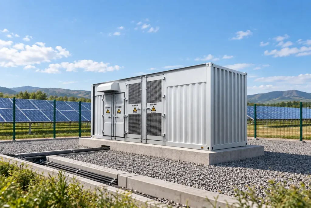
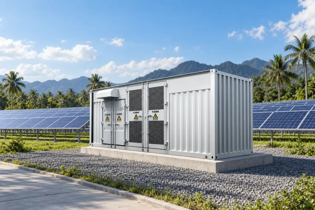
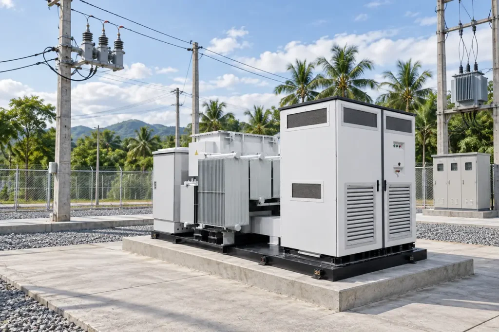
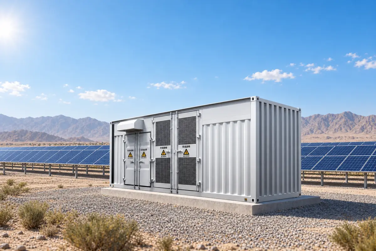
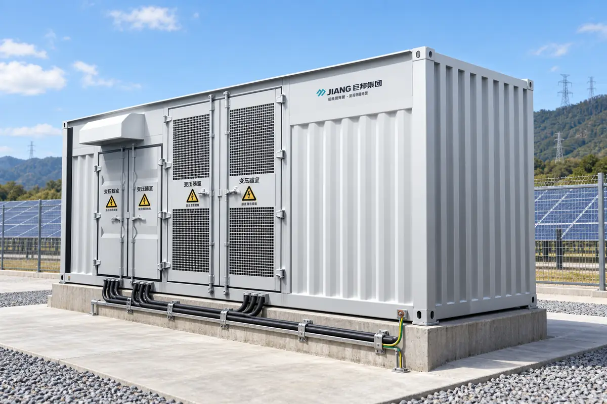
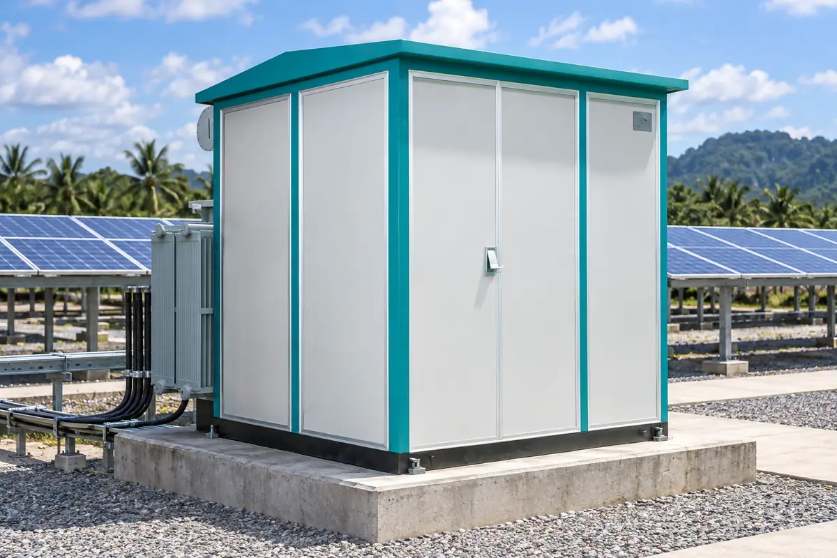
“European style” describes the arrangement and switching philosophy, not a universal voltage or an automatic compliance mark. A typical package places a power transformer, MV metal-enclosed switchgear, LV terminations, surge protection, metering, and a controller in coordinated compartments. The physical separation limits fault propagation and gives an EPC team a single tested interface between inverter output and the collector network.
Use a one-line diagram to freeze interfaces: inverter AC voltage and fault current, transformer vector group and impedance, MV rated voltage, earthing method, CT/VT classes, and communications. If the project needs station-level control, map IEC 61850 logical nodes or the owner’s protocol at the factory stage; do not leave point lists to site improvisation.
2. Where “low loss” is won—and where it disappears
Conductor and transformer losses
For a resistive path, Ploss = I²R. Illustrative case: a 2.5 MW block at 1,000 V has 2,500 A on the DC side; with a 35 m copper path (70 m loop) at 0.00008 Ω/m, R is 0.0056 Ω and loss is 35 kW. Moving the same power to 33 kV reduces current to about 43.7 A; a 120 m MV loop at 0.00035 Ω/m then loses about 0.13 kW. Actual values depend on conductor temperature, parallel runs, harmonics, and joints, so use the manufacturer’s impedance and the IEC 60287 ampacity method in the design model.
Transformer no-load and load losses are continuous costs. A 2,500 kVA unit with illustrative 2.0 kW no-load and 24 kW load loss at rated current consumes 2.0 kW even at night and 26 kW at full load. Compare guaranteed loss values at the purchase temperature and tap position; a small purchase-price premium can repay itself through 20-year energy value and lower cooling duty.
Harmonics, clipping and thermal derating
Inverter current distortion raises RMS current and hotspot temperature even when real power is below nameplate. Confirm the inverter’s current spectrum, transformer K-factor or thermal capability, and the point-of-common-coupling harmonic limits in the grid study. A station that clips at 2.5 MW because of a 2.4 MVA transformer or a conservative 40 °C rating loses revenue that a data-sheet efficiency percentage will not reveal.
3. Compact footprint versus serviceability
Compact means shorter interfaces, not zero access space. Reserve door swing, lifting points, cable-bending radius, and a safe working zone in the civil layout. IEC 60529 IP ratings apply to enclosure ingress protection; they do not prove arc-fault containment, corrosion resistance, or flood survivability. For an outdoor site, ask for the declared IP test configuration, drainage details, UV-resistant seals, and a corrosion class appropriate to the atmosphere.
| Design choice | Performance effect | Hidden cost or risk | Evidence to request |
|---|---|---|---|
| Integrated MV/LV package | Shorter cable runs; coordinated protection | Restricted access if compartments are too tight | General arrangement, heat-run report, maintenance clearances |
| Higher transformer impedance | Lower fault current | More voltage drop and possible inverter trips | IEC 60076 test values and system short-circuit study |
| Forced ventilation | Higher continuous loading in hot weather | Fan failure, dust ingress, auxiliary energy | Derating curve, alarm matrix, spare-fan strategy |
| Higher IP enclosure | Better dust/water exclusion | Harder heat rejection; pressure and seal maintenance | IEC 60529 test report and thermal calculation |
4. Match the station to the application
| Application | Typical decision | Commissioning focus | Commercial consequence |
|---|---|---|---|
| Utility PV, 33 kV collector | 2–3 MVA transformer blocks, ring or radial MV scheme | Vector group, anti-islanding, harmonic scan | Energy yield and grid-code acceptance |
| Commercial/industrial rooftop | Smaller oil-immersed or dry-type unit, constrained access | Noise, fire separation, arc-flash labels | Permitting and outage-cost exposure |
| Hybrid PV + BESS | Bidirectional protection and coordinated controls | State transitions, reverse power, communications loss | Availability and imbalance penalties |
| High-altitude or hot site | Altitude correction and enlarged cooling margin | Temperature-rise and insulation coordination | Avoided derating and premature insulation ageing |
5. Standards, compliance and failure modes
IEC 62271-200 addresses AC metal-enclosed switchgear above 1 kV and internal-arc classification; IEC 62271-1 provides common service and test requirements. IEC 60076-1 covers transformer general requirements, while IEC 60076-11 applies to dry-type transformers. IEC 60529 defines the IP code test method. IEC 61850 concerns power-utility automation communication, and IEC 61439 is relevant to low-voltage assemblies where the package includes an LV switchboard.
These standards are not interchangeable certificates. A type-test report for one cubicle arrangement cannot automatically validate a modified busbar, door, or transformer combination. Contractually define routine tests, witness points, short-circuit withstand, dielectric tests, CT polarity, interlocks, and software revision. Non-compliance can mean rejected energisation, retesting at the supplier’s cost, delayed revenue, or an insurance dispute after a fault.
Common field failures are diagnostic: harmonic alarms point to impedance and filter interaction; midday clipping points to an MVA or temperature limit; hot spots at cable lugs indicate torque, crimp, or ventilation problems; repeated earth-fault trips often trace to CT saturation or an incorrect neutral-earth scheme.
6. Selection and verification checklist
Hidden-cost check: Ask the bidder to show a 20-year loss model separating no-load, load, cable, auxiliary, clipping, and curtailment losses. Use the project’s hourly irradiance and ambient-temperature profile rather than a single peak-power point.
- Freeze electrical interfaces and grid-code functions in the one-line and data sheet.
- Require guaranteed transformer losses, impedance tolerance, temperature-rise limits, and altitude corrections.
- Review enclosure IP evidence, internal-arc classification where specified, corrosion protection, and drainage.
- Witness routine tests and a protection-injection test; archive settings, firmware, and signed trip records.
- Plan spares for fans, surge arresters, relays, fuses, and door seals, with response times in the O&M contract.
Jubang Electric can be evaluated as one source for configurable transformer and switchgear packages; start with the technical schedule and test evidence, then compare like-for-like scope. Relevant product context includes the ZGS/ZG-35 combined transformer, YB-12 intelligent integrated substation, and KYN28A-12 metal-clad switchgear.
7. FAQ
What is a grid-tie European inverter booster station?
It is a coordinated package that connects one or more PV inverters to a medium-voltage collector system through a step-up transformer, switchgear, protection, metering, and auxiliaries. “European” generally refers to the compact, compartmented arrangement; voltage, earthing, and grid functions still follow the project specification.
How do you calculate losses in an inverter booster station?
Sum inverter conversion loss, transformer no-load and load loss, cable I²R loss, switchgear and auxiliary consumption, and any clipping caused by thermal or MVA limits. Calculate each over an hourly operating profile; use measured or guaranteed test values and state assumptions.
What is the difference between a European and American style substation?
European packages commonly use metal-enclosed MV switchgear and a compact integrated transformer/inverter arrangement. American practice often uses outdoor transformers, separately mounted switchgear, and different utility conventions; neither style is inherently safer or more efficient without checking the applicable code and service conditions.
How does a compact substation improve PV project economics?
It can reduce cable length, civil footprint, installation interfaces, and commissioning time. The gain is real only when thermal capacity, access, spares, and protection coordination are preserved; otherwise service outages can exceed the installation saving.
What IP rating is suitable for an outdoor inverter booster?
Choose the IP code from dust, rain, washdown, and condensation exposure, commonly beginning at IP54 for sheltered outdoor enclosures and higher where water jets or dust are expected. Confirm the tested configuration and provide ventilation or heat-exchanger calculations so a higher IP rating does not create thermal derating.
How do you verify grid-tie protection settings?
Start with the approved load-flow, short-circuit, and anti-islanding studies. Inject secondary current/voltage into the relay, record pickup and trip times, test interlocks and communications-loss behavior, and obtain the utility’s signed settings approval before energisation.
8. References
- IEC 62271-200 and IEC 62271-1, metal-enclosed switchgear requirements.
- IEC 60076 series, power-transformer requirements and tests.
- IEC 60529, enclosure ingress-protection (IP) test method.
- IEC 61850 and IEC 61439 committee resources, automation and LV assembly scope.
Procurement gate: A low-loss station is proven by its loss schedule, thermal envelope, protection test records, and maintainable layout—not by a compactness claim alone.
Takeaway: Specify the interfaces, model the losses over time, and witness the tests before the first megawatt is exported. For a project review or quotation, contact Jubang Electric with your inverter data, MV collector voltage, site temperature, and grid-code settings.