JUBANG



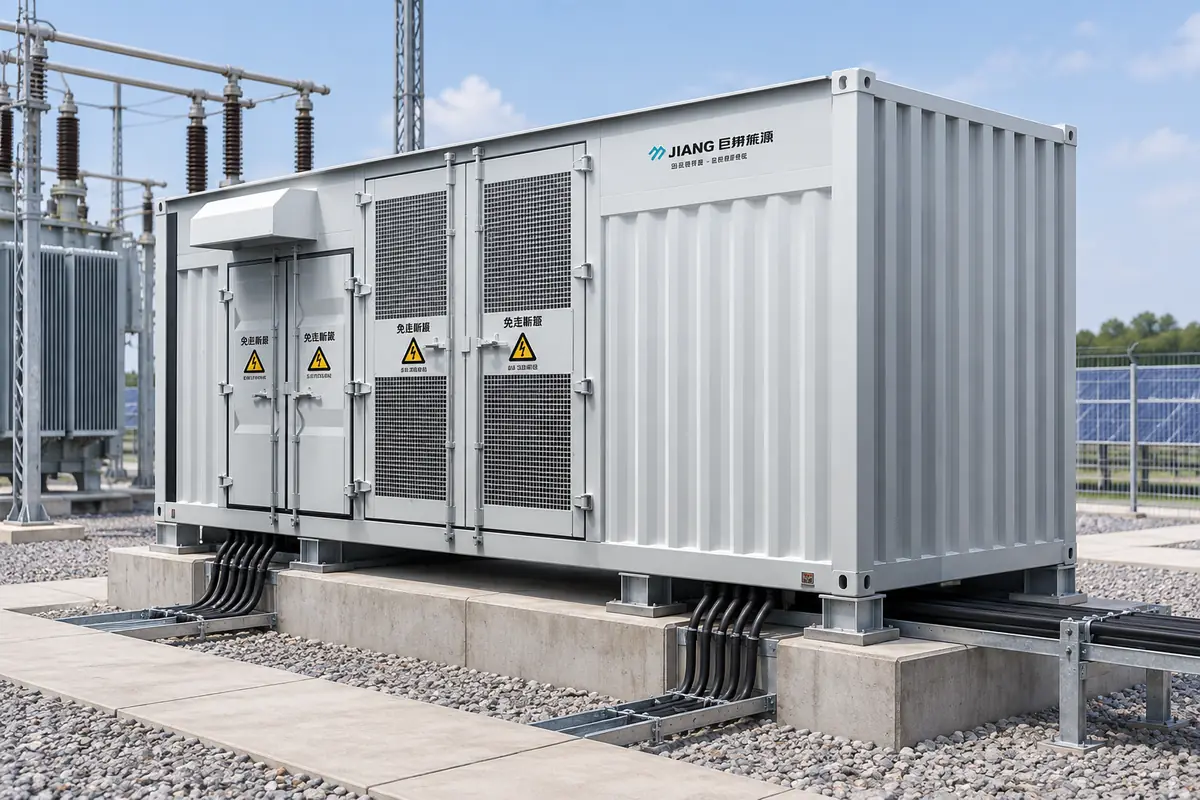
Medium Voltage Substation: European Style Inverter Booster Integrated Machine
When Aisha Rahman, electrical lead for a 120 MW solar project outside Al Ain, UAE, energised the first collector circuit, the protection relay tripped within seconds. The inverter passed its self-test, yet the MV breaker saw an unexpected neutral displacement and the commissioning team lost two days tracing a cable-screen bond. The reversal was important: the equipment was not simply “bad.” The package mixed an American-style transformer arrangement with a European-style protection scheme, and the interface, earthing and sizing assumptions had never been reconciled.
Summary: A European-style inverter booster integrated machine combines inverter output transformation, medium-voltage switching, protection and monitoring in a factory-engineered enclosure. For a solar block, specify the grid voltage, inverter fault current, cooling duty, earthing method and communications map before choosing a footprint. IEC 62271-200/62271-1 govern the MV assembly, IEC 60076-1/11 cover transformer design, and IEC 60529 defines the IP code; use those documents as acceptance criteria, not as a generic “IEC compliant” label.
In practical terms, the substation raises low-voltage AC from one or more PV inverters to the collector voltage—commonly 10, 12, 20 or 35 kV—then feeds a ring-main or radial collector. Integrating the functions reduces field wiring and crane lifts, but it also makes the specification more interdependent: a change in transformer impedance can alter breaker duty, relay settings and voltage-drop calculations.
What the integrated machine contains
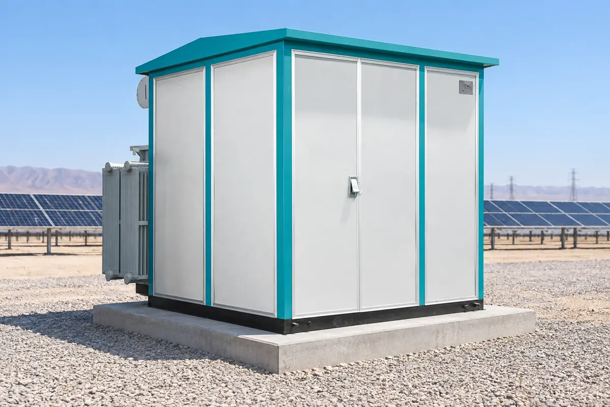
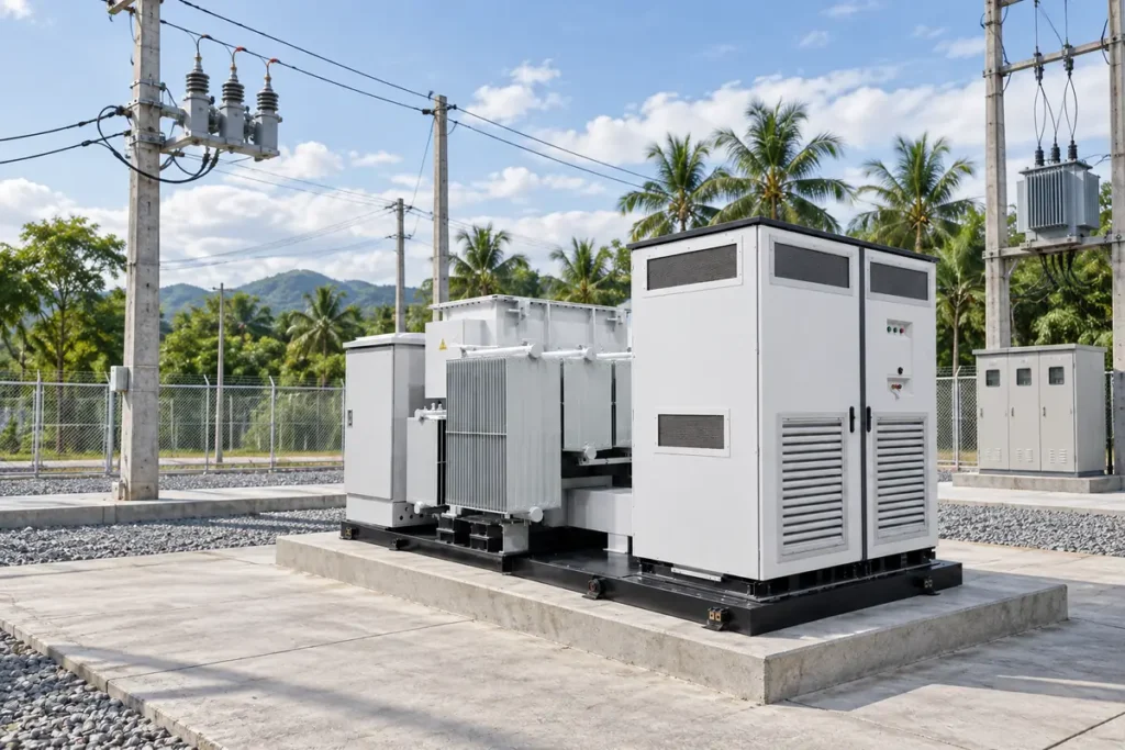
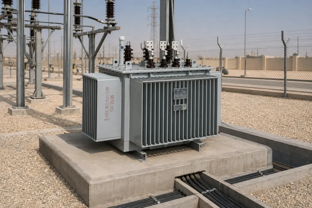
The low-voltage compartment receives inverter feeders, surge protection and auxiliary power. A cast-resin or oil-immersed transformer then provides galvanic isolation and the voltage step-up. On the MV side, metal-clad switchgear typically includes a load-break or circuit breaker, earth switch, cable compartment, CTs/VTs and a protection relay. A single skid or kiosk may also carry thermal sensors, a local HMI and a gateway to the plant SCADA.
Factory integration is useful when a project has repeated 2–6 MVA blocks: the wiring diagram, interlocks and routine tests can be standardised. It is less attractive when the utility requires a bespoke bay arrangement, indoor arc classification or a transformer that cannot share the enclosure heat budget. Confirm service access and fire separation early; a compact footprint that cannot accommodate a hot-work or oil-spill response is not a real saving.
Electrical sizing with transparent assumptions
Start with the inverter apparent-power total, then apply a design margin for ambient temperature, clipping strategy and reactive-power obligations. Size from the grid interface backwards: first establish the permitted MV voltage and short-circuit level, then select transformer rating, impedance and switchgear withstand.
Illustrative calculation: assume four 1.25 MVA inverters, 0.95 power factor at the grid interface, 40 °C design ambient and a 10% continuous margin. Required transformer rating is 4 × 1.25 × 1.10 = 5.50 MVA; select the next standard rating (for example 6.3 MVA) only after checking overload duration and cooling class. At 35 kV, a 6.3 MVA three-phase transformer carries approximately I = 6,300 kVA ÷ (√3 × 35 kV) = 104 A on the MV side. The LV current at 0.8 kV is about 4,546 A, so busbar segmentation and parallel inverter feeders matter more than the MV cable ampacity alone.
Short-circuit duty must use the utility’s declared fault level, not a catalogue default. Transformer impedance affects prospective current: at 6.3 MVA and 8% impedance, the transformer-limited current at its LV terminals is approximately 6,300 kVA ÷ (√3 × 0.8 kV × 0.08) ≈ 56.8 kA, before upstream network impedance. Treat this as an illustrative upper bound; the protection study should include inverter current-limiting behaviour, cable length and the utility X/R ratio.
Protection, interfaces and environmental design
Specify the protection functions by operating scenario: overcurrent and earth-fault (50/51, 50N/51N), under/over-voltage (27/59), frequency (81) and anti-islanding or transfer-trip logic where required by the grid code. The relay map should identify CT ratios, class, polarity, trip-coil supervision and breaker-failure logic. IEC 61850 communication is valuable when the utility accepts IEC 61850 logical nodes and a tested station-bus design; otherwise, a hardwired trip and a documented protocol gateway may be more robust.
For outdoor sites, IP54 may protect against harmful dust ingress and splashing, while IP55 or IP65 can be justified for wind-blown dust, wash-down or monsoon exposure—provided pressure-relief paths, door gaskets and cable glands are tested as installed. IP code does not prove corrosion resistance, arc performance or thermal endurance. Ask for the enclosure test report, salt-fog or coating specification where coastal exposure is expected, and a maintenance method that does not defeat the seal.
Hidden cost and total-cost logic
The purchase order is only one line in the project budget. Compare engineering hours, civil foundations, cable termination kits, factory witness testing, customs volume, spare parts and the cost of a delayed energisation. A useful project model is:
Illustrative TCO = equipment + transport/cranage + civil works + commissioning labour + expected outage energy + five-year maintenance.
Suppose a 5.5 MVA block exports at 90% utilisation during a 10-hour solar window and a commissioning delay costs 2 days. Lost energy is 5.5 MW × 0.90 × 10 h × 2 = 99 MWh. At an assumed project value of US$45/MWh, the delay exposure is US$4,455—before liquidated damages. If an integrated design cuts one day of field wiring but adds a specialist relay engineer for acceptance, the decision should use these explicit assumptions rather than a blanket “lower installation cost” claim. Compare the same TCO boundary: transformer losses, warranty response, spares and test scope must be like-for-like.
Value comparison: European and American style arrangements
| Dimension | European-style integrated machine | American-style pad-mounted arrangement |
|---|---|---|
| Switching/protection | Metal-clad MV cubicle, visible isolation and relay panel; suited to utility-defined interlocks. | Often dead-front pad-mounted gear with compact switching; configuration varies by utility. |
| Footprint and civil work | One engineered kiosk can reduce interfaces; foundation still needs cable bend and access zones. | Separate or integrated pad equipment can be simple to place but may require different clearances. |
| Maintenance | Front-access compartments and documented test points support planned outages. | Fewer exposed MV parts, but proprietary elbows, fuses or controls may affect spares. |
| Grid compatibility | Flexible CT/VT, relay and IEC 61850 options when specified early. | Strong fit where the utility standardises pad-mounted interfaces. |
| TCO tendency | Higher engineering discipline up front; potential savings in repeated blocks and commissioning. | Potentially low civil complexity; interface changes can increase redesign and outage cost. |
Dimension and application guide
| Application | Typical block assumption | Design focus |
|---|---|---|
| Rooftop or C&I PV | 0.5–2.5 MVA, 10–12 kV collector | Noise, fire separation, access and utility anti-islanding. |
| Utility-scale desert PV | 2.5–6.3 MVA, 20–35 kV collector | Dust sealing, 50 °C derating, thermal imaging and spare filters/gaskets. |
| Floating or humid PV | 1–5 MVA, 10–35 kV collector | Condensation control, corrosion coating, cable buoyancy and drainage. |
| Hybrid PV-plus-storage | 2–6.3 MVA bidirectional duty | Four-quadrant reactive power, harmonics, reverse power and black-start sequence. |
Standards, procurement and first-brand decision
Use IEC 62271-200 for AC metal-enclosed switchgear assemblies above 1 kV and IEC 62271-1 for common service conditions and test principles. IEC 60076-1 sets general transformer requirements; IEC 60076-11 applies to dry-type transformers. IEC 60529 defines the IP code test classification, while IEC 61850 specifies information models and communication services—not a blanket approval of a complete substation.
Unsupported compliance language can trigger utility rejection, retesting, warranty disputes or import delays. Request the exact routine/type-test schedule, test laboratory and report scope; verify the tested configuration matches the offered busbar, enclosure and transformer options. The European Committee for Electrotechnical Standardization (CENELEC) adoption and the destination utility code may add requirements beyond the IEC base text.
- Freeze the single-line diagram, earthing philosophy and utility fault level before requesting quotations.
- Issue a data sheet covering altitude, ambient, solar clipping, harmonic limits, IP target, cable entry and communications.
- Require a protection coordination file, heat-run assumptions, interface list and FAT witness points.
- Price a five-year spares and response plan, including relay settings backup and replacement glands.
At this stage, Jubang can be evaluated as a configurable source for the YB-12 intelligent integrated substation, with related options such as a ZGS/ZG-35 PV combined transformer or KYN28A-12 metal-clad switchgear. Confirm ratings, test documents and utility acceptance for the exact configuration; product pages are a starting point, not a substitute for the project data sheet.
Frequently asked questions
What is a Medium Voltage Substation?
It is an installation that switches, protects and transforms electricity at distribution voltages above 1 kV and typically up to 36 kV in solar collector systems. It links inverter or generator feeders to a plant collector or utility point of interconnection. The voltage class, fault level and utility rules determine the equipment selection.
What is an inverter booster integrated machine?
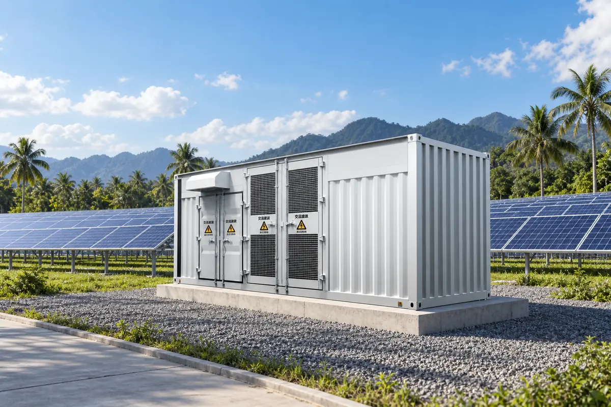
It is a factory-coordinated package combining inverter-side connection, step-up transformer, MV switchgear, protection and auxiliaries in one enclosure or skid. Integration can shorten field wiring, but the thermal, earthing and control interfaces must be engineered as one system.
How does a European style inverter booster substation work?
Low-voltage AC from the inverter enters a transformer, rises to the collector voltage, and passes through a metal-clad MV cubicle with CTs/VTs, breaker and earth switch. A relay trips the breaker for defined faults and reports status locally or through SCADA. The exact sequence follows the utility protection and interlocking schedule.
What is the difference between a European and American style substation?
European-style packages commonly use accessible metal-clad MV switchgear with explicit isolation and relay compartments; American-style pad-mounted designs often use dead-front interfaces and utility-specific elbows or fuses. Neither is universally superior—the deciding factors are local codes, maintenance practice, fault duty and spare-parts availability.
How do you size a medium voltage substation for solar power?
Sum inverter apparent power, apply a documented continuous margin, then verify transformer thermal duty, voltage drop, harmonics, fault current and reactive-power requirements. Check both LV bus current and MV breaker/cable withstand; use the utility short-circuit study rather than a catalogue assumption. Recalculate for clipping, high ambient and storage reverse power when applicable.
What IP rating is suitable for an outdoor inverter booster?
IP54 is a common baseline for sheltered outdoor enclosures; dusty, wash-down or monsoon locations may justify IP55 or IP65. Select the rating with the gland, door, pressure-relief and ventilation design, and verify the installed assembly by test evidence. IP rating alone does not address corrosion, arc classification or transformer cooling.
References
- IEC 62271-200, AC metal-enclosed switchgear and controlgear for rated voltages above 1 kV and up to 52 kV.
- IEC 62271-1, common specifications for high-voltage switchgear and controlgear.
- IEC 60076-1 and IEC 60076-11, power and dry-type transformer requirements.
- IEC 60529, degrees of protection provided by enclosures (IP Code).
- IEC 61850, communication networks and systems for power utility automation.
Commissioning succeeds when the single-line diagram, test evidence and operating reality agree. If your EPC or utility team is defining that decision now, review the GT-GIS-12 gas-insulated switchgear option and contact Jubang Electric for a configuration review against your grid code, fault study and site conditions.