JUBANG



When Omar Haddad, an EPC commissioning lead in Al Kharsaah, Qatar, closed the container doors before the noon export test, the inverter booster tripped on over-temperature within 18 minutes. A portable fan kept the block online long enough to inspect it, but dust alarms returned after the next cleaning cycle. The reversal was in the specification, not a defective inverter: the enclosure was treated as an indoor room, the transformer derating used a 40 °C assumption, and cable glands were not matched to the dust-control plan.
Summary: A containerized European inverter booster combines inverter-side connections, a step-up transformer, medium-voltage (MV) switchgear, protection and auxiliaries in a transportable enclosure. For desert PV, design around the real ambient (often 45–50 °C), dust loading, maintenance access and the utility fault level; IEC 62271-200/1, IEC 60076-1/11 and IEC 60529 define useful evidence boundaries. Treat IP54 as an ingress test class, then prove heat rejection, sealing and service procedures before committing to a compact footprint.
What a containerized European booster station contains
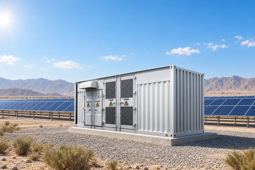
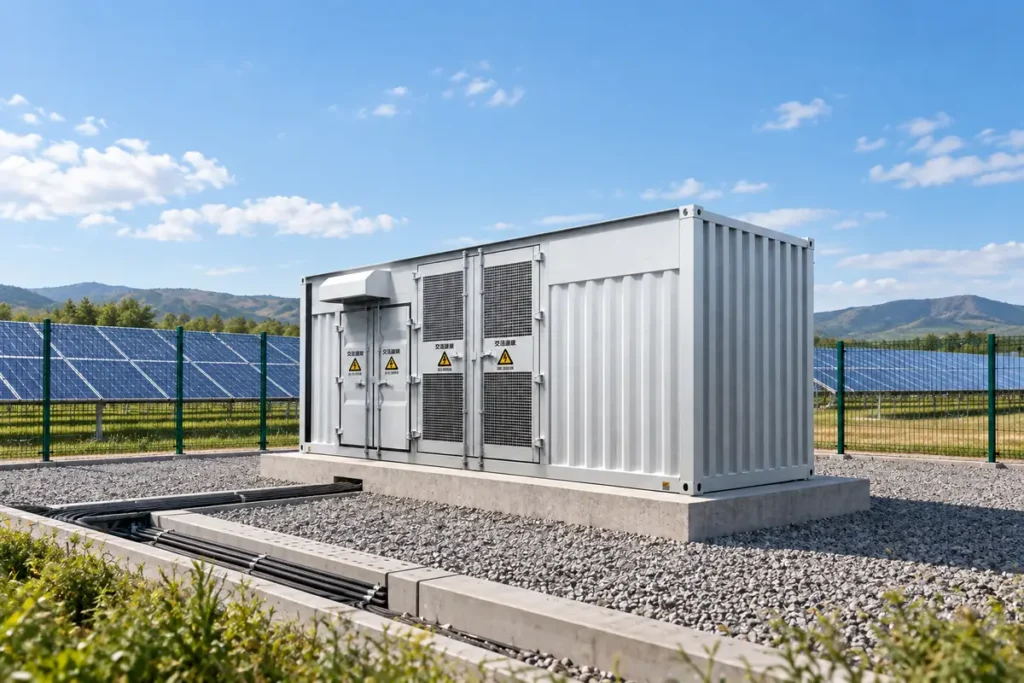
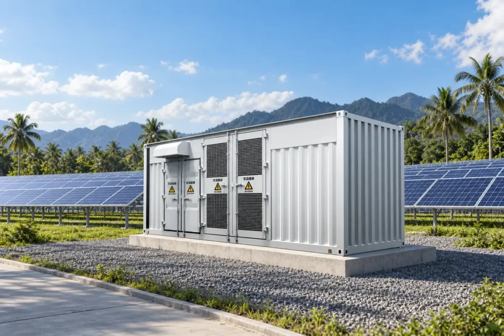
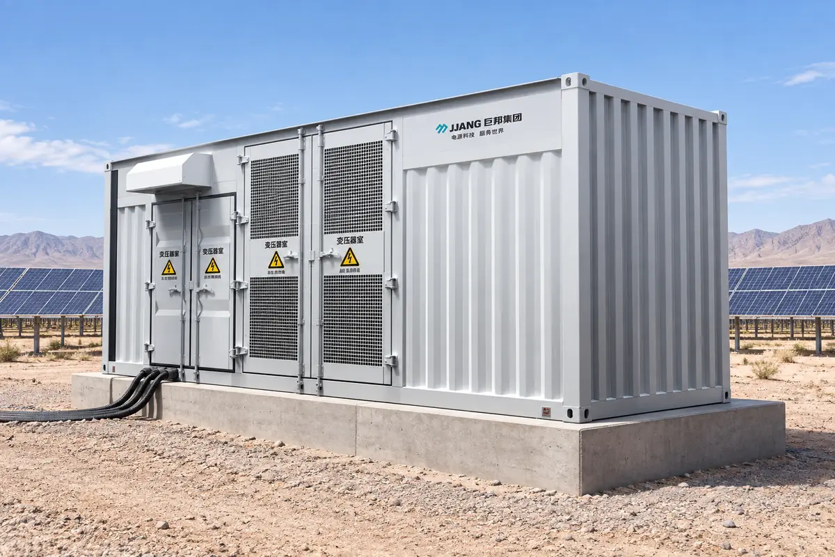
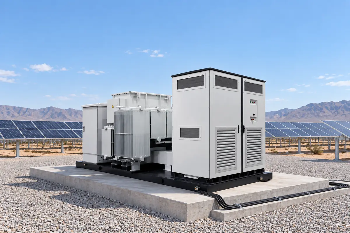
A typical container has separate LV/inverter, transformer and MV compartments. It receives inverter feeders, provides voltage step-up and isolation, then switches the collector circuit through a breaker or load-break switch, earth switch, CTs/VTs and relay. A gateway and environmental sensors connect the station to SCADA.
“European” describes a compartmented operating arrangement rather than a universal product standard. Freeze the one-line diagram, earthing method, vector group, impedance, CT classes, communications map and utility interlocks together; changing impedance or gland dimensions can alter protection coordination or enclosure evidence.
Desert dust and heat: design for the failure modes
IP54 is a starting point, not a thermal guarantee
IEC 60529 defines protection against solid objects and water for a tested enclosure configuration. IP54 can be reasonable for a maintained outdoor compartment, but the code does not prove UV resistance, corrosion protection, arc performance or transformer temperature rise. Wind-blown sand enters through doors, pressure-relief paths, cable glands and fan filters; each opening must be specified and inspected as an installed system.
Higher IP values can reduce dust ingress while making heat rejection harder. Ask for a thermal calculation at declared ambient, roof solar gain, altitude and loading; then compare filtered ventilation, heat exchangers or air-conditioning with their auxiliary energy, filter intervals and failure alarms.
Typical field symptoms and root causes
Midday over-temperature trips often point to blocked filters, undersized fans, transformer losses or a container roof that has become a solar collector. Repeated earth-fault alarms can follow dust tracking across insulators, a degraded gland seal or a neutral-earth arrangement that differs from the protection study. Hot cable lugs usually indicate torque, crimp, conductor temperature or ventilation issues rather than an inverter firmware fault. Record the alarm, weather, load, compartment temperature and last-cleaning date before replacing parts.
Electrical sizing with transparent assumptions
Start with maximum inverter apparent power, reactive-power obligations and clipping strategy. Apply ambient and altitude derating, then verify voltage drop, harmonics, transformer impedance and MV short-circuit withstand. For an illustrative block of four 1.25 MVA inverters, a 10% continuous margin gives 4 × 1.25 × 1.10 = 5.50 MVA; a 6.3 MVA transformer may be the next standard step only after its 50 °C cooling class and overload duration are confirmed.
At 35 kV, 6.3 MVA carries about 104 A (6,300 kVA ÷ √3 ÷ 35 kV). At 0.8 kV LV, the same rating is approximately 4,546 A, so busbar segmentation, parallel feeders and termination heating are central design items. An 8% impedance gives an illustrative LV transformer-limited current near 56.8 kA before upstream impedance; the protection study must include inverter current limiting, cable length and the utility X/R ratio.
Value comparison: European container versus American-style pad mount
| Dimension | Containerized European arrangement | American-style pad-mounted arrangement | What to verify |
|---|---|---|---|
| Compartment and access | Separate LV, transformer and MV rooms; front or side service points | Often a sealed transformer tank with dead-front interfaces | Isolation sequence, door clearance and cable bend radius |
| Dust and heat | Filters, heat exchangers and room-by-room thermal design | Sealed tank limits exposed live parts but can constrain field repair | IP test configuration, derating curve and alarm response |
| Protection flexibility | Relay, CT/VT and ring-main options can follow the utility study | Fuses, elbows and controls often follow local utility conventions | Fault duty, settings file and spare compatibility |
| Civil and logistics | One transportable package; foundation and lifting frame are coordinated | Pad and cable entries may be simpler for a standard utility design | Crane route, foundation loads and customs dimensions |
| TCO tendency | More engineering up front; potential savings in wiring and commissioning | Lower interface count for a standard pad; proprietary parts can extend outages | Losses, spares, labour, downtime and five-year service cost |
Application and dimension matrix
| Application | Typical block range | Environmental focus | Commissioning evidence |
|---|---|---|---|
| Desert utility PV | 1.6–6.3 MVA; 20–35 kV collector | 45–50 °C ambient, sand, UV, low humidity | Heat-run data, filter plan, IP report and relay injection |
| Coastal or humid PV | 0.63–5 MVA; 10–35 kV collector | Salt mist, condensation and corrosion coating | Coating specification, heaters, drains and insulation checks |
| Rooftop or C&I PV | 0.25–2.5 MVA; constrained access | Noise, fire separation and short cable routes | Acoustic data, fire plan, room ventilation and FAT records |
| PV plus battery feeder | 1–6.3 MVA bidirectional duty | Frequent cycling, reverse power and harmonics | Overload cycle, state-transition and SCADA tests |
Standards, compliance and total-cost logic
Use IEC 62271-200 for AC metal-enclosed MV switchgear and optional internal-arc classification; IEC 62271-1 provides common ratings and test principles. IEC 60076-1 covers general transformer requirements, while IEC 60076-11 applies to dry-type transformers. IEC 60529 defines the IP-code test method. None of these standards is a blanket certificate for a modified container, and a report for one busbar or gland arrangement should not be assumed to cover another.
Request routine and agreed type-test reports, calibration traceability, heat-run assumptions, dielectric results, CT polarity, interlock checks and a deviation list. Non-compliance can trigger utility rejection, retesting, customs questions, warranty disputes or delayed revenue. Confirm the destination grid code and any local fire, seismic or environmental rules in addition to IEC documents.
Model TCO across the same boundary: equipment, transport and cranage, civil works, cable kits, commissioning labour, auxiliary energy, transformer losses, planned maintenance, spare filters and the cost of outage energy. An illustrative two-day delay for a 5.5 MW block at 90% utilisation and 10 export hours per day represents 99 MWh of deferred energy (5.5 × 0.90 × 10 × 2). Apply the owner’s project value and contractual exposure; do not present this example as a guaranteed loss.
Selection guide and supplier evaluation
- Freeze inverter AC voltage, maximum kVA, reactive range, harmonic spectrum, MV voltage, earthing and fault level in one interface schedule.
- Set the environmental envelope: design ambient, altitude, solar gain, dust-cleaning method, humidity, corrosion category and IP target for each compartment.
- Require general-arrangement drawings with door swing, lifting points, cable bend radius, drains, pressure relief and safe isolation clearances.
- Witness routine tests and protection-injection tests; archive relay settings, firmware, trip times and communications-loss behaviour.
- Price a five-year plan for filters, gaskets, fans, surge arresters, relays, fuses and emergency response, then compare expected downtime.
Specify dust control as a maintainable process. Jubang Electric can be included in a like-for-like enquiry using the YB-12 intelligent integrated substation, the ZGS/ZG-35 PV combined transformer and KYN28A-12 metal-clad switchgear as configuration references. Confirm exact ratings, transformer type, IP evidence and utility acceptance for the issued quotation; product pages do not replace a project data sheet.
Frequently asked questions
What is a containerized European inverter booster?
It is a transportable, factory-coordinated package combining inverter connections, a step-up transformer, MV switchgear, protection, metering and auxiliaries. European style usually refers to separated, accessible compartments and a coordinated switching philosophy; voltage, earthing and utility rules still control the design.
Is IP54 enough for desert PV?
IP54 can be a baseline for a maintained outdoor enclosure, but it is not automatically enough for wind-blown sand, high solar gain or wash-down. Verify the tested doors, glands and pressure-relief paths, then add thermal, UV, corrosion and filter requirements for the actual site.
How do you protect inverter booster equipment from dust?
Use compartment seals, correctly rated cable glands, filtered ventilation or a sealed heat exchanger, positive-pressure control where justified, and a documented cleaning interval. Monitor differential pressure and compartment temperature; replace filters and gaskets before they become a trip cause.
What is the difference between a European and American style substation?
European-style packages commonly separate LV, transformer and MV functions in a coordinated container or kiosk with accessible switchgear. American-style pad-mounted designs often use sealed transformer tanks and dead-front interfaces; local utility practice, fault duty, maintenance skills and spare availability should decide.
How do you size a booster transformer for a solar plant?
Start with inverter apparent power, reactive-power range and clipping, then apply ambient and altitude derating. Check transformer losses, impedance, voltage drop, harmonics, MV fault withstand and bidirectional duty where storage is present; select a standard rating only after those checks.
What maintenance does a containerized booster station need?
Inspect seals, glands, filters, drains, fans, heaters, oil level or dry-type windings, cable torque and protection settings at intervals set by the OEM and site conditions. Add thermal scans, insulation and relay tests, alarm-log review and spare-part replacement after dust storms or abnormal temperature events.
References
- International Electrotechnical Commission, IEC 62271-200 and IEC 62271-1.
- International Electrotechnical Commission, IEC 60076-1 and IEC 60076-11.
- International Electrotechnical Commission, IEC 60529, Degrees of protection provided by enclosures (IP Code).
- IEC Electropedia, terms and definitions for power transformers and switchgear.
Use test evidence to make compactness credible. The reliable desert booster is the one whose interfaces, thermal envelope, dust-control routine and protection records match the operating site. When your EPC or utility team is ready to compare a containerized design, contact Jubang Electric with the inverter data, collector voltage, fault study and site climate.