JUBANG



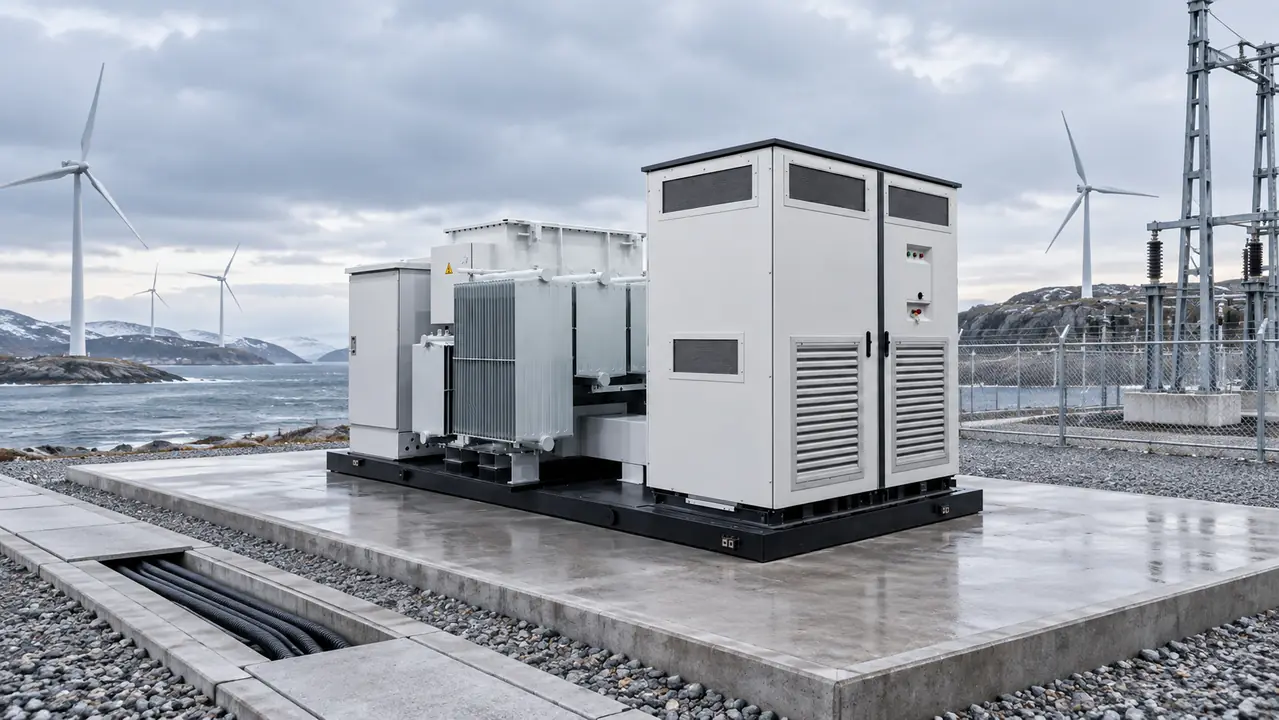
When commissioning manager Elena Park at a wind-plus-storage project outside Ulaanbaatar energized the first booster skid after a night at −28°C, the medium-voltage feeder tripped and the battery stopped following its wind-ramp command. Warming the enclosure did not solve the problem. A protection review reversed the initial diagnosis: the hardware was not simply defective; cold-start auxiliaries, transformer inrush, and relay settings had been specified as separate items instead of one operating system.
Summary: A factory-integrated skid can move work off-site, but it does not eliminate route surveys, foundation control, cable termination, protection studies, or commissioning. Buyers should define the package efficiency boundary, source of energization, cold-start auxiliary load, and interface owner before comparing offers. IEC 62933 provides a system-level energy-storage framework, while IEC 62271-202 and IEC 60076-1 address different equipment scopes; none replaces project-specific acceptance criteria. The practical recommendation is to contract the skid, studies, settings, FAT, SAT, and as-left records as one traceable delivery.
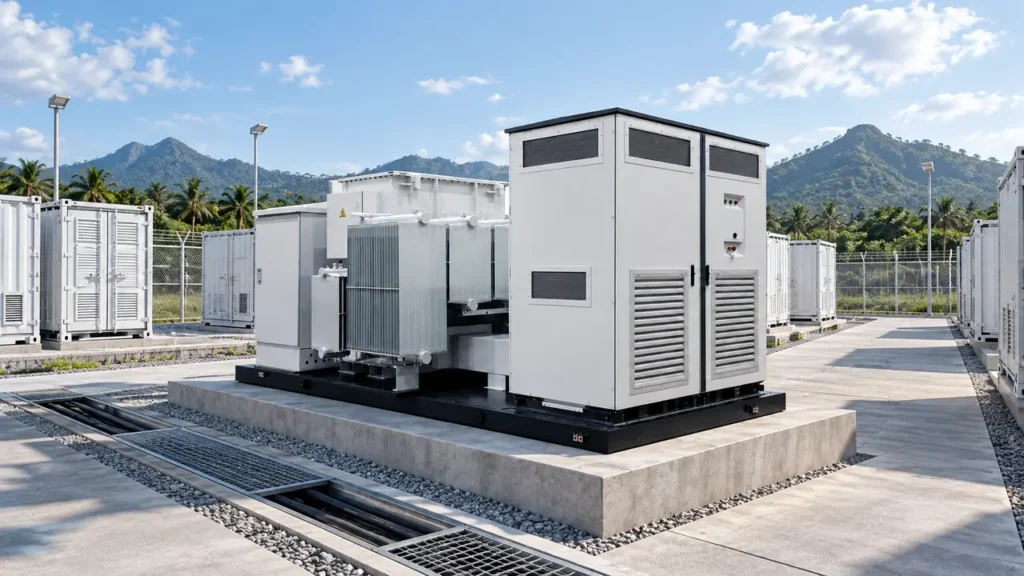
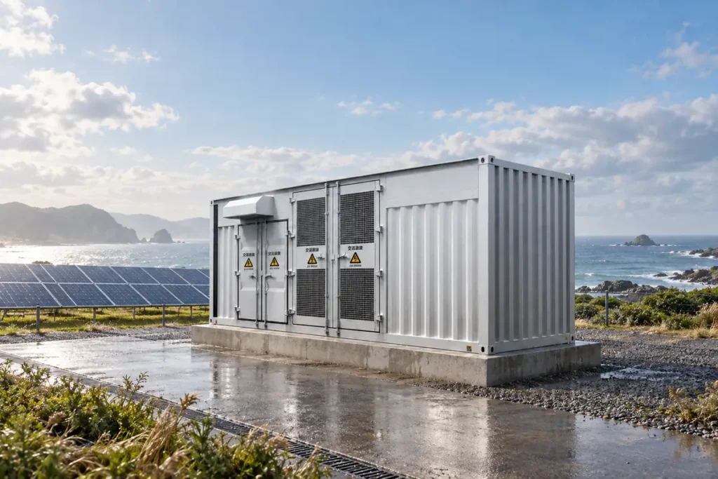
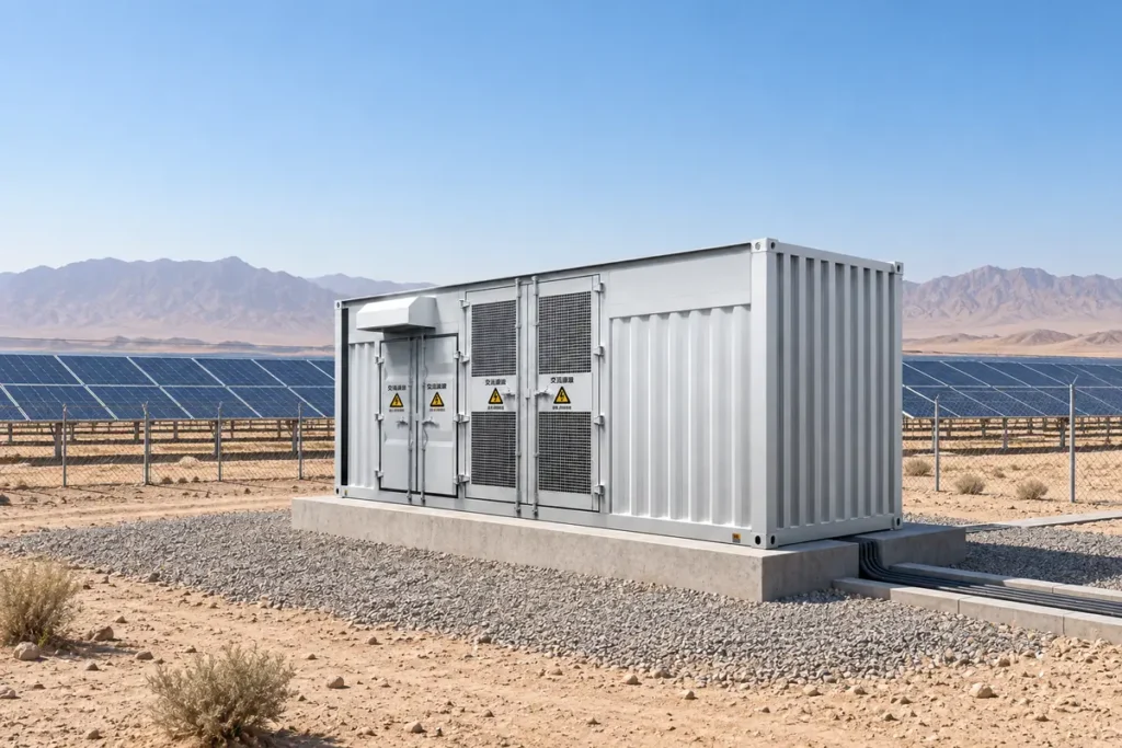
A Skid-mounted American energy storage converter booster fast installation package normally combines a power conversion system (PCS), step-up transformer, medium-voltage switching, controls, protection, and auxiliary services on a transportable base. It converts battery DC into controlled AC and raises voltage for the wind-farm collector. “American style” describes a compact combined-transformer arrangement in this context; it is not, by itself, evidence of compliance with any national code or project specification.
How Does Factory Integration Change Site Work Rather Than Remove It?
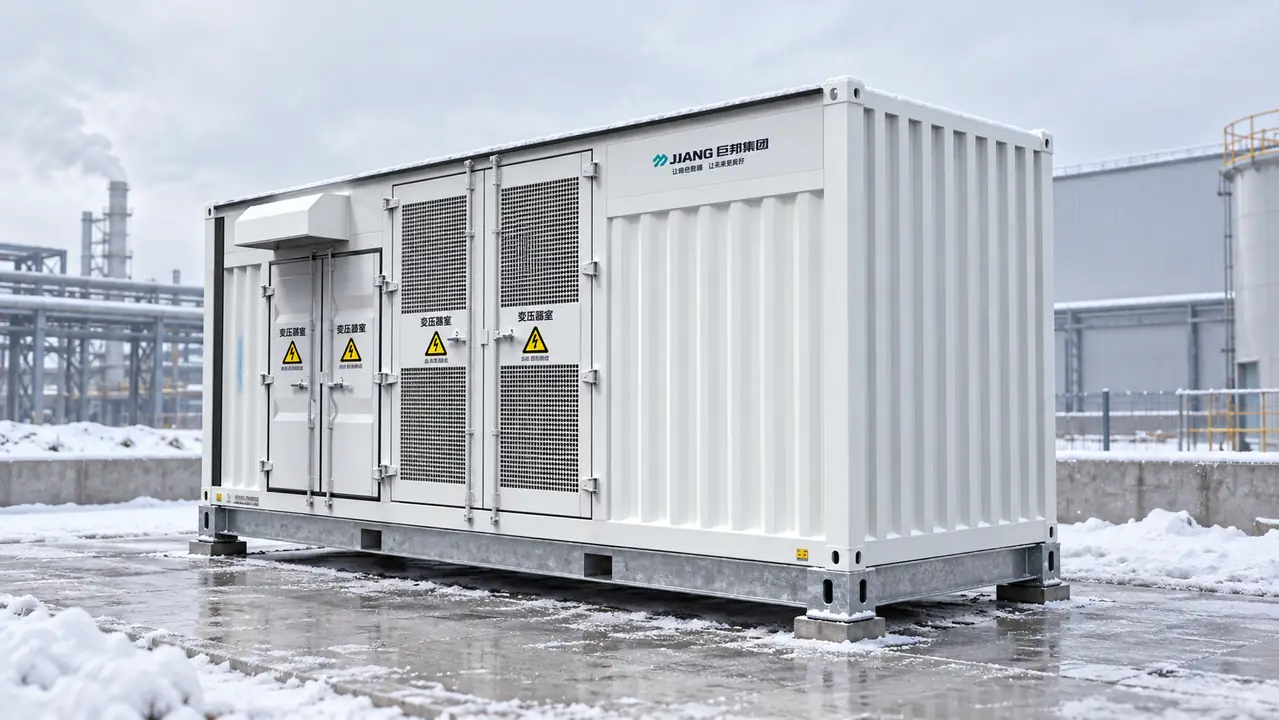
Factory assembly can complete internal fit-up, wiring, labeling, interlocks, and selected functional checks in a controlled environment. The remaining site scope is still substantial: unload and set the skid, verify foundation level and anchor locations, connect DC and AC power cables, terminate control and communication circuits, bond the grounding system, supply station service, load approved settings, and prove behavior against the plant controller. A credible schedule therefore separates factory-complete work from site-complete work instead of calling the unit “plug and play.”
The logistics boundary starts before shipment. State shipping mass and dimensions, transport split, center of gravity, lifting points, temporary bracing, shock monitoring, and preservation. The EPC should verify road and bridge limits, last-mile turns, gradients, crane capacity at final hook radius, and laydown space. If modules must be removed for transport, name who reinstalls and retests them.
The civil boundary needs measurable foundation elevation, flatness, anchor, grounding, drainage, snow-clearance, and cable-trench tolerances. Cable scope should assign supply and termination and define conductor size, bend radius, gland or connector, shielding, bonding, fiber type, tests, and spares. Any mismatch can erase the factory schedule advantage.
Consider an illustrative schedule calculation: if factory integration removes eight site days for a six-person crew at USD 850 per person-day and avoids two crane days at USD 6,500 per day, the apparent saving is (8 × 6 × 850) + (2 × 6,500) = USD 53,800 per block. This is not a quotation. Oversize transport, route reinforcement, civil rework, extra cable length, tax, or a repeated commissioning test can reverse the result.
Size the Whole Electrical Package, Not Isolated Nameplates
Check PCS continuous power, overload duration, DC-voltage window, reactive duty, derating, and fault behavior separately from transformer MVA. Transformer rating must account for power factor, harmonics, cooling, temperature rise, impedance, losses, and dispatch. Auxiliaries are a third load category and must be deducted when power is guaranteed at the MV connection point.
A PCS peak-efficiency value is not a package guarantee. Define the measurement boundary, power direction, load, DC voltage, power factor, ambient condition, transformer tap, meter accuracy, stabilization period, and treatment of HVAC, heaters, pumps, fans, controls, and station-service losses. State whether the result is point, weighted, or duty-cycle efficiency.
For an illustrative efficiency calculation: assume 10.00 MW enters the PCS, PCS efficiency at the agreed point is 98.2%, transformer efficiency is 99.2%, and operating auxiliaries draw 80 kW. The measured export would be approximately (10.00 × 0.982 × 0.992) − 0.08 = 9.661 MW, or 96.61% across that defined boundary. These assumed values are not product guarantees; they show why two high component efficiencies do not establish the net package result.
An American style energy storage booster for wind farm smoothing also needs a control boundary. If a 50 MW plant is limited to a 10% nameplate change per minute, the permitted change is 5 MW/min. A 12 MW one-minute fall implies about 7 MW of BESS response, subject to state of charge, measurement point, delay, and inverter limits. This sizes one event; time-series data and the dispatch rule determine energy capacity.
Which Cold-Start and Auxiliary Loads Can Delay Energization?
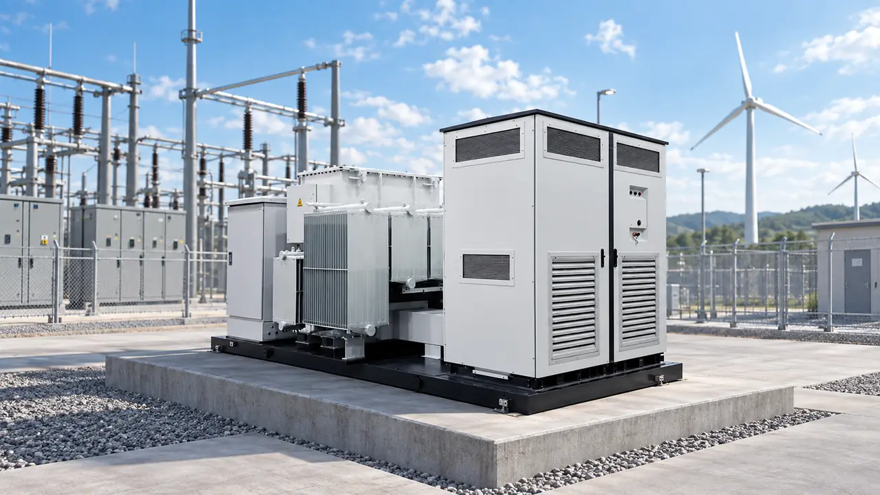
Distinguish transport, storage, de-energized survival, cold energization, and normal operating limits. Low temperature can affect liquid viscosity, seals, breaker mechanisms, sensors, control batteries, power supplies, and condensation control; review component limits and manufacturer procedures for the offered build.
The auxiliary-load schedule should list heaters, transformer controls, HVAC, pumps where used, fire controls, communications, relays, breaker motors, and trace heating. Record running and starting power, diversity, duration, voltage, and whether each load precedes PCS operation. Station service and backup DC must support the simultaneous cold-start sequence, not only normal running demand.
Name the first energizing source. A healthy grid may supply station service before the main transformer; weak-grid or black-start duty may require a grid-forming source for preheat and controls. Restore station service, controls and communications, the reference source, transformer and MV bus, critical loads, then non-critical loads. Define permissives, pickup, inrush, abort criteria, and ownership at each step.
Because PCS current limits differ from rotating-generator behavior, the inrush model should cover residual flux, transformer and feeder impedance, grounding, PCS limits, relay measurement, and source strength. Acceptance tests must prove the agreed energization cases without settings that mask genuine faults.
Compare Integrated and Field-Assembled Delivery Against the Same Scope
| Buyer decision | Factory-integrated skid | Field-assembled package |
|---|---|---|
| Work location | More internal wiring, fit-up, and checks completed before shipment | More alignment, cabling, and integration completed at the project site |
| Transport and lifting | Larger shipping envelope and concentrated lift require early route proof | Smaller deliveries may simplify access but create more handling events |
| Foundation and cables | Interface locations must match the prefabricated base precisely | Layout can adapt later, with more field engineering and termination work |
| System testing | Integrated FAT can expose control and interlock issues before dispatch | Full-system behavior is usually demonstrated later during site integration |
| Change management | Repeated blocks are efficient; late physical changes can affect the whole assembly | Phased procurement can be flexible but increases coordination ownership |
| Lifecycle access | Compact arrangement demands verified withdrawal paths and service clearances | Spacing may suit local maintenance practice but uses more site area |
| Total-cost tendency | May reduce site labor and weather exposure while increasing freight or crane cost | May reduce oversize logistics while increasing installation and commissioning effort |
Compare bids on the same battery and PCS boundary, MV termination, auxiliaries, studies, settings, tests, spares, preservation, and commissioning support. Price or risk-adjust exclusions before treating the lowest equipment price as the lowest delivered cost.
Assign Every Interface Before Release for Manufacture
| Interface | Decision the schedule must record | Required handover evidence |
|---|---|---|
| PCS and plant controls | Setpoint owner, ramp logic, reactive-power priority, communications, time sync, and loss-of-signal state | I/O list, protocol map, logic narrative, simulation results, and approved firmware |
| Protection settings | Study owner, relay functions, grading margins, PCS fault model, inrush restraint, and approval authority | Protection study, settings files, checksums or revision IDs, and test sheets |
| Transformer | Ratio, vector group, impedance tolerance, losses, taps, grounding, thermal duty, and energization source | Guaranteed data, routine-test report, loss data, thermal/derating curves, and inrush assumptions |
| MV switchgear | Rated voltage, insulation level, short-time duty, internal-arc requirement, interlocks, cable entry, and earthing | Applicable type-test references, routine tests, drawings, and interlock matrix |
| Auxiliaries and HVAC | Supply source, cold-start demand, diversity, redundancy, alarms, and recovery after outage | Load schedule, single-line diagram, heat-load basis, and start sequence |
| Communications and cybersecurity | Network boundary, remote access, accounts, ports, event records, patching, and backup ownership | Network diagram, point list, access procedure, backup, and approved version baseline |
| Grounding and civil works | Skid bond, neutral grounding, touch/step study inputs, foundation tolerance, drainage, and cable trench boundary | Grounding drawing, study inputs, foundation loads, interface drawing, and site survey record |
There is no universal allocation among the skid supplier, PCS supplier, EPC, owner, and grid operator. Assign one accountable party to each input, approval, and field action, with due dates and document revisions; “by others” is not an owner.
Make FAT, SAT, and the Settings Baseline Contract Deliverables
The minimum evidence package should include the approved single-line, interface drawings, protection study, load-flow and fault models, transformer impedance and losses, thermal and derating curves, harmonic assumptions, auxiliary-load schedule, grounding inputs, spares, and test plan. Identify model formats and software versions needed to reproduce results.
FAT should verify traceability, wiring, applicable routine tests, interlocks, alarms, trips, metering, emergency stop, communication loss, controller I/O, cooling controls, and representative protection logic. It cannot prove final cables, site grounding, the grid interface, or full plant-controller response, so it does not replace SAT.
SAT should verify received condition, installation, terminations, insulation, grounding continuity, phase rotation, auxiliaries, CT/VT circuits, relay injection, breaker operations, communications, controller commands, fail-safe states, and charge/discharge steps. Energization tests need approved hold points and diagnostic oscillography or trend data.
Record settings baselines at FAT, approval for energization, and the as-left stage. Identify relay files, firmware, parameter exports, logic revisions, network configuration, deviations, and backup location. Review every change between stages, and apply the same control after firmware or controller replacement.
IEC 62271-202 covers qualifying prefabricated substations above 1 kV and up to 52 kV. IEC 60076-1 gives general transformer requirements, while the IEC 62933 series addresses grid-integrated storage across multiple parts. Name the applicable editions, clauses, tests, and acceptance values; a standards list alone does not prove project compliance.
Use a Procurement Gate to Select the Right Booster Package
- Freeze the measurement boundary, DC range, continuous and overload duty, collector voltage, power factor, fault level, grounding method, harmonics, control objective, and grid-code inputs.
- Issue the route survey, lifting limits, foundation and cable interface drawings, altitude, operating and storage temperatures, snow, solar load, humidity, pollution, seismic, corrosion, and acoustic conditions.
- Approve the interface-responsibility schedule, study assumptions, protection philosophy, cold-start sequence, auxiliary-load schedule, and package efficiency test method before manufacture.
- Witness or review FAT evidence, close deviations before shipment, and preserve a controlled firmware and settings baseline.
- Release energization only after SAT proves installation, protection, communications, controls, fail-safe behavior, and required performance at the contractual boundary.
At this later selection stage, Jubang Group can support configuration review for a GTE-ZGS energy storage power conversion and step-up integrated unit, a 35 kV wind power combined transformer, and compatible KYN61-40.5 metal-clad switchgear. Suitability should be established from project-specific drawings, declared ratings, studies, test records, and the agreed responsibility boundary—not inferred from a product family name.
Resolve These Six Buyer Questions Before Approval
What is a Skid-Mounted American Energy Storage Booster?
It is a transportable package that integrates power conversion, voltage step-up, medium-voltage connection, auxiliaries, controls, and protection on a skid or compact base. The exact supply boundary varies, so the contract must state whether batteries, MV switchgear, protection panels, cooling equipment, station service, and external cables are included.
What voltage do wind turbines use before grid connection?
Many turbine generators or converters produce low-voltage output that is stepped up near the turbine and collected at a project-specific medium voltage, which may be 33 kV or 35 kV. The value depends on the turbine platform, collector design, and interconnection requirements; buyers should use the approved single-line diagram rather than a generic industry value.
Why are combined transformers used in wind farms?
They combine transformer and switching functions in a compact assembly, which can reduce field interfaces and land use. Their project value still depends on transport access, fault duty, foundation accuracy, cable scope, service clearances, environmental design, and whether integrated factory testing reduces site risk.
How do low temperatures affect wind power transformers?
Low temperature can affect liquid viscosity, seals, instruments, switching mechanisms, heating time, and condensation behavior during warm-up. Specify transport, storage, cold energization, and normal operating limits separately, then verify the offered liquid, components, heaters, sensors, and loading sequence against those conditions.
What protection equipment is integrated in a wind farm substation?
A project may use overcurrent and earth-fault elements, transformer differential or restricted earth fault where applicable, temperature and pressure devices, surge arresters, breaker controls, and metering. The final scheme depends on grounding, transformer construction, PCS fault-current behavior, CT/VT design, source strength, and the grid operator’s coordination rules.
How do you select a wind turbine step-up transformer?
Match rated power, voltage ratio, vector group, impedance, insulation level, losses, harmonic duty, temperature rise, overload profile, ambient conditions, switching duty, and protection interfaces to the turbine or storage system and collector. Require project study models, guaranteed data, routine-test evidence, and agreed energization procedures before approval.
Use These Primary Sources to Verify Contract Language
- International Electrotechnical Commission, IEC 62933 series search for electrical energy storage systems.
- International Electrotechnical Commission, IEC 62271-202 search for high-voltage switchgear and controlgear—prefabricated substations.
- International Electrotechnical Commission, IEC 60076-1 search for power transformers—general requirements.
Procurement rule: the fastest skid is the one whose route, foundation, cable boundary, cold-start behavior, settings, and acceptance evidence are settled before it reaches the site.
For a configuration review aligned with your wind-farm smoothing duty, collector voltage, climate, and delivery route, contact Jubang Group with the single-line diagram, site-condition schedule, and proposed interface matrix.