From transformers and switchgear to ring main units, substations, circuit breakers and smart components, Jubang provides integrated product support for power distribution projects.
Discover Jubang’s strengths in technology R&D, quality testing and smart manufacturing, supporting reliable electrical equipment and efficient power distribution solutions for global customers.
From technical consultation and OEM/ODM customization to EPC support, smart O&M, delivery documentation and after-sales service, Jubang supports your project at every stage.
Explore Jubang Group’s development history, intelligent manufacturing base, R&D platforms, CNAS-accredited laboratory and global project service capabilities.
Prefabricated Substation Layout: Cable Routing, Access and Maintainability
Release Time: 2026-07-14
A prefabricated substation layout should turn the electrical single-line diagram, site constraints and service concept into a documented enclosure arrangement—not simply place equipment in the smallest available housing. Start with the circuits, cable interfaces and maintenance tasks that must be performed safely throughout the asset life; then confirm the enclosure family with the project engineer, owner and applicable requirements.
Part 1. What should a prefabricated substation layout achieve?
The layout must reconcile the incoming network interface, transformer, MV and LV equipment, auxiliary/control systems, cable entries and service activities. IEC 62271-202 applies to enclosed AC prefabricated substations within its stated voltage scope and recognizes both walk-in and externally operated types. That distinction should be a design decision, not an afterthought.
Use four outcomes to review a concept:
Outcome
Question to resolve
Evidence to retain
Electrical interface
Can every circuit be terminated, identified, tested and earthed as required?
Single-line diagram, termination schedule and cable schedule
Civil interface
Do entry sides, base openings, transport and lifting align with the site?
General arrangement and foundation/interface drawing
Service interface
Can the planned operator inspect, isolate, operate and replace the intended components?
Task list, door/panel drawing and maintenance plan
Future interface
Are documented spare ways or expansion provisions actually needed?
Owner load plan and approved design revision
ABB notes that MV/LV substation design combines electrical, mechanical, construction and installation work. Treating those as one review package avoids discovering a route or access conflict after the enclosure is fabricated.
In buyer and utility documents, a prefabricated substation may also be called a Compact Secondary Substation (CSS). Treat CSS as a product-family description, then verify the actual assembly, operating concept and applicable standard edition. Where internal-arc performance is relevant, IEC 62271-202 uses an internal-arc classification (IAC); the project specification must state whether IAC is required and the intended classification. Do not infer it from the enclosure name, a CSS label or a different quoted configuration.
Part 2. Which decisions must be made before choosing an enclosure?
Freeze the interfaces before selecting a product family: system voltage and single-line diagram; transformer and switchgear configuration; entry direction; cable types and terminations; owner operating method; climate/site conditions; and service responsibilities. A product catalogue can support concept selection, but it cannot fill in absent project data.
Ask for the following enclosure characteristics in the RFQ or project specification when they matter:
Characteristic
What to request
Do not assume
Internal-arc classification (IAC)
Whether IAC is required, the intended classification and the applicable IEC 62271-202 basis
That a prefabricated substation or CSS label includes IAC performance
IP degree of protection
The required IP degree for the relevant enclosure and the applicable basis under IEC 60529
One IP degree for every door, compartment, cable entry or site condition
Ventilation class
The required ventilation class and the quoted assembly documentation that supports it
That natural or forced ventilation is suitable for the transformer duty and ambient conditions
Partition class
The required partition class and the compartments or interfaces to which it applies
That a visible barrier represents a particular partition class
IEC 62271-202-related enclosure characteristics are configuration- and project-dependent. The supplier should confirm the classifications offered for the submitted assembly, and the responsible project parties should confirm that they meet the installation, operating and approval requirements.
The first coordination meeting should assign ownership for each boundary:
Interface
Questions for the project team
Typical owner to confirm
MV supply
Incoming circuits, terminations, screening/earthing and outage procedure?
Utility / EPC electrical lead
Transformer and LV
Rating, connections, LV feeder count and protection interfaces?
Electrical designer / equipment supplier
Controls and communications
RTU, protection, metering, SCADA and fiber/copper pathways?
Protection / automation lead
Civil works
Base, cable-entry interface, drainage, transport and lifting limits?
Civil lead / installer
Operations
Normal switching, emergency access, inspection and replacement tasks?
Asset owner / operations team
For a product-family starting point, see JUBANG’s Prefabricated Substations category. The final arrangement still needs current model documentation and approved project drawings.
Part 3. How should cable routes be planned without generic rules?
IEEE 525 treats substation cable systems as a design, installation and protection topic that includes routing, raceways, segregation and maintenance. Apply that mindset by creating a route record for every circuit rather than adopting a universal aisle width, clearance, trench geometry or cable-separation value.
Group cables by function—power, protection/control, metering, communications and auxiliaries—then document the reason for each route decision. Redundant paths, electromagnetic compatibility, fire strategy, pullability, termination access and future modifications can change the preferred arrangement. The applicable standard, network owner and project engineer set the actual routing rules.
A practical cable-route schedule should include:
Circuit reference and source/destination.
Function, voltage class and redundancy role.
Cable construction, outside diameter, minimum handling data and termination type from the approved cable/equipment documents.
Entry point, route medium, ownership boundary and pull direction.
Earthing/screen bonding approach, identification and test requirements.
Inspection access, route changes, crossovers and unresolved interfaces.
Part 4. How should cable entry and termination interfaces be documented?
Cables fail at interfaces when drawings only say “bottom entry” or “rear entry.” The general arrangement should show the enclosure orientation, entry zone, relevant removable sections or panels, termination-side access and the interface to the base or external route. The cable schedule then supplies the circuit-level data that the physical drawing cannot carry.
The Ellevio secondary-substation specification is an example of a purchaser document that addresses component access, cable connection and maintenance. Its requirements are specific to that owner and setting; use it as a prompt for questions, not as a universal design template.
Before finalizing the layout, reconcile the following:
equipment termination drawings and permitted cable/terminal arrangements;
cable pulling and installation method from the installer;
base/foundation entry interface and sealing/drainage responsibilities;
bonding and earthing design;
test access, labeling and as-built records; and
changes made after factory acceptance, transport or site installation.
Part 5. What makes access maintainable over the operating life?
Maintainability means the intended team can perform the intended tasks with the correct isolation, tools, access controls and replacement path. It is broader than door placement. List normal operation, inspection, testing, fault response, cable work, component removal and cleaning; then test the layout against each task.
IEC 62271-202 includes structural and access-related considerations for the substations within its scope, while project and local safety requirements decide the final arrangement. A walk-in enclosure may provide internal access, but it does not automatically solve operating safety, tool clearance, ventilation, lifting or unauthorized-access risks. An externally operated arrangement may better fit some sites. Choose the service concept first.
Part 6. How should the layout be reviewed before procurement?
Run a cross-functional review before procurement and repeat it when the cable schedule or single-line diagram changes. The review should close conflicts, record assumptions and identify who approves each external interface.
Review discipline
Review question
Electrical
Are ratings, protection, earthing and all circuit destinations consistent with the approved single-line diagram?
Cable / installation
Are cable construction, route, entry, termination and installation constraints recorded for every circuit?
Mechanical / civil
Are base interfaces, enclosure orientation, doors/panels, transport and replacement paths coordinated?
Operations
Are operation, isolation, inspection and emergency tasks reviewed with the actual asset owner?
Documentation
Do the GA, cable schedule, termination schedule, interface matrix, test plan and revision register agree?
Fit boundary: This guide is suitable for early planning and RFQ preparation for a prefabricated substation. It is not a construction drawing, cable-sizing calculation, protection/earthing study, local-code interpretation or a promise that a generic clearance, trench or separation arrangement will be accepted. Final design requires the responsible project engineer, the owner/utility requirements and current equipment documentation.
Part 7. Which JUBANG route should be considered before an RFQ?
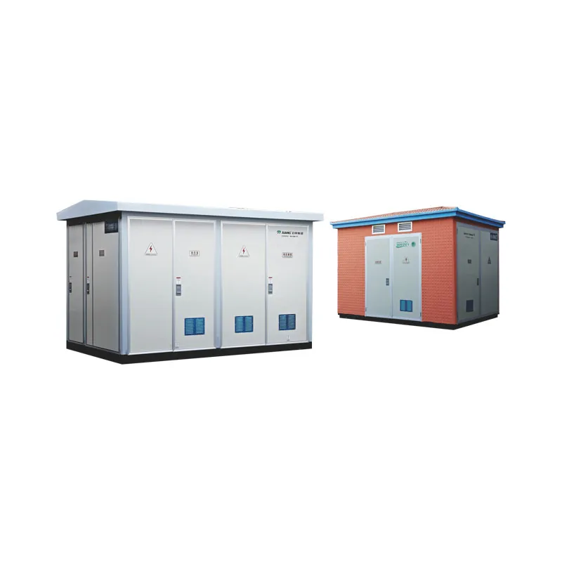
For an integrated prefabricated-substation concept, begin with the YB□-12 Intelligent Integrated Substation. For a box-type switching/ring-main starting point, review the XGW□-12 Box-Type Switching Substation. These are product-family routes, not automatic matches: suitability depends on the approved electrical scheme, cable interfaces, site constraints, applicable standards and current JUBANG documentation.
Send the following RFQ inputs through Online Message for a project-specific review:
Project location, service conditions, owner/utility requirements and applicable standards.
Approved or preliminary single-line diagram, system voltage/frequency and earthing/protection information.
Transformer, MV/LV switchgear, control, metering and communication interfaces.
What information must be in a prefabricated substation layout package?
At minimum, coordinate the single-line diagram, general arrangement, cable schedule, termination schedule, foundation/interface drawing, earthing concept, operating/maintenance task list and revision register. The owner and applicable rules may require more.
Should MV, LV and control cables share one route?
Do not decide from a generic rule. Assign routes by circuit function and evaluate segregation, redundancy, EMC, fire strategy, installation and maintenance against the project requirements and applicable standards.
Does a walk-in enclosure always simplify maintenance?
No. It may support internal access, but the intended tasks, operating method, safety controls, tools, ventilation and replacement path must still be reviewed.
What should be checked at the cable-entry interface?
Confirm entry side, base/interface drawing, cable and termination data, installation/pulling approach, sealing and drainage responsibilities, earthing/bonding, labeling and test access. Do not infer universal opening or trench dimensions.
Can the enclosure be selected before cable data is available?
Only as a preliminary concept. Final selection should wait until the cable schedule, entry arrangement, equipment interfaces and service concept have been reviewed.
What belongs in a supplier RFQ?
Provide the location and standards, single-line diagram, equipment interfaces, cable schedule, civil interface, operating/maintenance requirements, documentation/testing scope, quantity and commercial delivery information.
When is this article not enough?
When a project needs final construction details, cable calculations, protection/earthing studies, local permitting or owner acceptance criteria. Engage the responsible engineering and approval parties.
Products are exported to more than 100 countries and regions such as Africa, the Middle East, and the United Kingdom and Europe. It is a leading manufacturer of power distribution equipment in China.

 JUBANG