From transformers and switchgear to ring main units, substations, circuit breakers and smart components, Jubang provides integrated product support for power distribution projects.
Discover Jubang’s strengths in technology R&D, quality testing and smart manufacturing, supporting reliable electrical equipment and efficient power distribution solutions for global customers.
From technical consultation and OEM/ODM customization to EPC support, smart O&M, delivery documentation and after-sales service, Jubang supports your project at every stage.
Explore Jubang Group’s development history, intelligent manufacturing base, R&D platforms, CNAS-accredited laboratory and global project service capabilities.
Dry-Type Transformer Partial Discharge: What a Test Report Should Show
Release Time: 2026-07-19
A dry-type transformer partial discharge test report is insulation-test evidence, not a stand-alone promise about service life or fitness for energization. It should connect the reported apparent-charge result to the identified transformer, the test circuit, applied-voltage sequence, calibration record, background-noise conditions and the agreed acceptance basis.
Part 1. Start with the evidence boundary
Partial discharge is a localized electrical discharge that only partly bridges insulation. In a dry-type transformer test, the report records electrical evidence obtained under a defined test arrangement; it does not directly measure the physical charge at a possible discharge site.
IEEE C57.124 addresses detecting partial discharge in dry-type transformers and measuring associated apparent charge at the terminals during applied AC-voltage testing. IEC 60270 provides the wider charge-based measurement framework, including measurement circuits, calibration and discrimination from external interference.
The practical review question is not “Does this report contain a low number?” It is “Can a qualified reviewer trace the number to the tested transformer and the controlled conditions that produced it?” If that connection is absent, the record cannot support a reliable comparison with the agreed test plan.
Evidence that stays within scope
A report can show that a defined object was tested using a stated method and measuring arrangement.
It can record apparent-charge readings, test voltages, calibration and observed interference conditions.
It cannot, by itself, certify every insulation feature, locate a source, prove future field behavior or replace the acceptance decision assigned in the contract.
Part 2. Read apparent charge in its test-circuit context
IEC 60270 defines apparent charge as the quantity that would produce the same instrument reading if injected at the terminals of the test object in the specified test circuit. It is normally expressed in pC, but it is not the local charge involved at a discharge site.
That definition matters when comparing reports. Change the object connection, coupling arrangement, measuring impedance, frequency band, calibration position or interference environment, and a pC figure may no longer mean the same thing for a review purpose.
Report item
What it tells the reviewer
What it cannot establish alone
Apparent-charge reading
The stated measurement-system response at the documented condition
Defect size, exact location or lifetime
Test voltage and sequence
The electrical condition at which the reading was recorded
A generic acceptance limit for every design
Measuring bandwidth and circuit
How the electrical measurement was arranged
That another laboratory will obtain an identical trace
Acceptance basis
Which controlled requirement was used for the decision
Compliance with requirements not named in the plan
Avoid asking a supplier to apply one value to every dry-type transformer. The applicable standard edition, transformer design, contractual specification, applied-voltage sequence and acceptance authority must be named before a criterion can be evaluated.
Part 3. Match the report to the actual test object
Before reading a trace, verify that the report identifies the transformer well enough to prevent a document mix-up. The report number, test date, manufacturer identity, transformer serial number and nameplate details should point to the same object named in the purchase and test documentation.
Electrical identity is equally important. Record the winding arrangement, rated voltages, terminal designations, tap position where relevant, grounded or ungrounded terminals, accessories connected during the test and any declared configuration that can affect the electrical arrangement.
Report fields that make a test traceable
Field group
Include in the report
Review action
Transformer identity
Manufacturer, type, serial number, ratings and winding information
Match to the purchase data and nameplate record
Tested configuration
Terminals energized, terminals grounded, tap position and connected accessories
Match to the approved test plan
Test facility
Laboratory identity, date and responsible test personnel
Retain with witness and deviation records
Measuring system
Detector, coupling device, measuring impedance, calibrator and instrument identifiers
Confirm the stated equipment matches the calibration record
Result record
Voltage points, apparent-charge readings, traces and observations
Check that every result has a condition and evaluation basis
Nameplate work is a useful precursor to this check. The distribution transformer nameplate guide explains why ratings and connection data should be controlled before technical records are compared.
Part 4. Check calibration, background noise and setup
Calibration ties the instrument scale to a known injected charge in the stated arrangement. The record should identify the calibrator, its status, the injected value or values, the injection location and the response obtained before the measurement run. A calibration statement without the test-circuit context is incomplete evidence.
Background noise and interference need their own record. IEC 60270 distinguishes signals caused by the test object from extraneous signals, so the report should show how the baseline was observed, what noise level or pattern was present, and what action was taken when interference affected interpretation.
Setup questions for a report review
Is the test circuit or connection diagram included and legible?
Are coupling components, measuring impedance, detector and calibrator identified?
Does the calibration entry state the injected charge and connection point?
Is the background condition recorded before or during the relevant measurement?
Are unexplained pulses, repeating patterns or excluded intervals described rather than silently removed?
Does the report distinguish an observed signal from a conclusion about the transformer?
Where the test uses a temporary connection, confirm cable routing, shielding and grounding arrangements in the test record. These details can affect the interference environment and should be reviewed by the responsible test authority rather than inferred from a final result table.
Part 5. Keep voltage sequence, traces and criteria together
The voltage history belongs beside the result. A report should state the test voltage levels, sequence, duration or dwell where specified, phase or terminal under test, and the point at which each trace or apparent-charge value was captured. A result table without this sequence is difficult to compare with a controlled plan.
Phase-resolved patterns, time-domain records or other traces can help show the observed signal behavior. They remain supporting evidence: their interpretation depends on the instrument settings, noise environment, calibration and qualified engineering review.
Controlled input
What the report should show
Why it matters
Applicable document set
Standard edition, purchaser specification and agreed test procedure
Prevents a generic criterion from replacing the agreed one
Voltage sequence
Applied levels, order, duration where required and result point
Links each result to its electrical condition
Trace record
Trace type, associated terminal or phase and time or voltage reference
Preserves the observation for review
Evaluation statement
Stated criterion and named decision authority
Separates laboratory measurement from project acceptance
Deviation record
Any change to the agreed setup, sequence or data quality
Makes escalation possible before release
IEC 60270 is a horizontal measurement standard; IEC 60076-11 and the purchaser’s controlled specification provide the transformer-specific context. Use those documents as inputs to a test plan, not as a reason to copy a universal pC limit into an RFQ.
Part 6. Separate factory evidence from field diagnosis
Factory PD measurement is commonly planned around a known transformer, controlled connections, defined equipment and an agreed production or witness procedure. Its value is the documented evidence for that defined test event.
Field diagnostic work may have a different purpose. Site connections, nearby electrical activity, installation condition, access constraints and background interference can all change the method and the confidence needed to interpret a signal. A field test authority should define the method, safety controls, comparison basis and action thresholds for the actual site.
Do not compare a factory result and a field result as if they were interchangeable simply because both use pC. First establish whether the object configuration, circuit, calibration, voltage condition and interference treatment are sufficiently comparable for the stated engineering decision.
Part 7. Turn the report into a controlled request package
An RFQ or witness request should ask for the report format before the test starts. This lets the purchaser, manufacturer and test authority agree which object identifiers, circuit records, calibration evidence, traces, acceptance inputs and deviations must be retained.
RFQ and test-plan checklist
Transformer type, ratings, winding arrangement, terminal designations and serial-number format
Required standard editions and purchaser specifications, including the order of precedence
Test-object configuration, connected accessories, grounding and terminal treatment
Applied-voltage sequence, result points and required trace format
Measurement-circuit diagram, detector, coupling components, measuring impedance and bandwidth
Calibrator identity, calibration record, injected-charge values and injection location
Background-noise observation method, interference notes and data-exclusion rules
Report template, witness hold points, deviation process and document-retention requirements
Named authority for evaluation, disposition of anomalies and energization decisions
If a report is missing an identifier, circuit diagram, calibration record, noise explanation, trace reference or agreed evaluation basis, pause the release decision and escalate the gap to the responsible test or engineering authority. Requesting a new conclusion without resolving the missing evidence can conceal the actual decision risk.
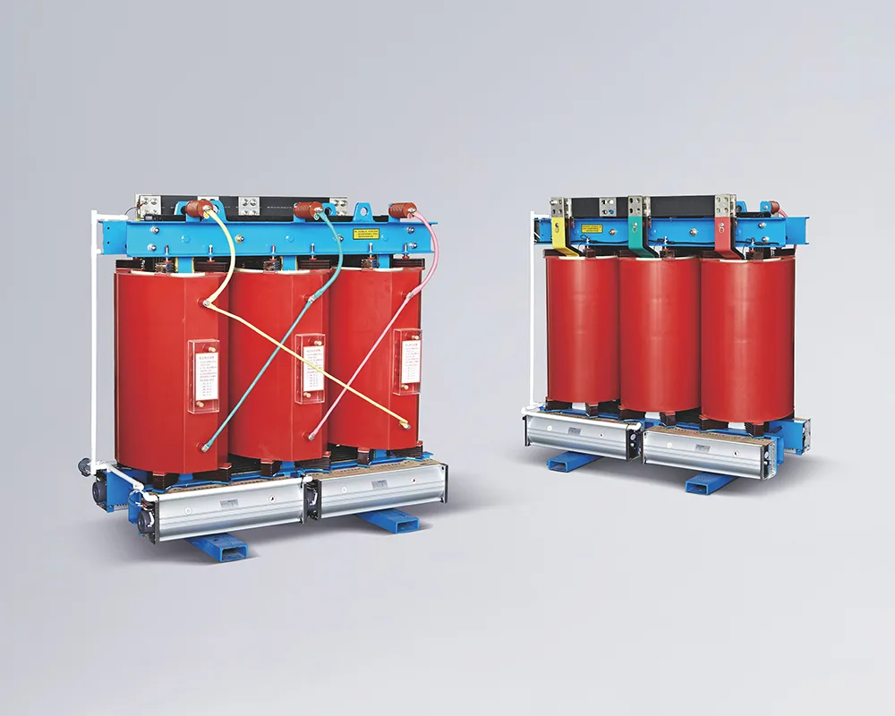
Once the equipment scope and documentation requirements are defined, a JUBANG SCB dry-type transformer range can be discussed as product-family context. It should not be treated as evidence of partial-discharge performance, a test result, a standard claim or a substitute for the controlled test plan.
Fit Boundary
Use this guide to define what a dry-type transformer PD report should contain and to prepare a documentation request. Do not use it to set an acceptance value, diagnose a site signal, locate a discharge source, certify a transformer or authorize energization.
For a project-specific documentation discussion, contact JUBANG with the transformer data sheet, controlled test plan, required standard edition, report template and the named acceptance authority.
FAQs
What is a dry-type transformer PD test?
It is a dielectric-test measurement that detects electrical PD signals and records apparent charge at transformer terminals under a defined AC test arrangement. Its meaning depends on the identified test object, circuit, voltage sequence, calibration and evaluation basis.
What is apparent charge in a PD report?
Apparent charge is the charge-related quantity that gives the same measuring-instrument response when injected at the test-object terminals in the specified circuit. It is commonly reported in pC, but it is not a direct measurement of local discharge charge or defect size.
Why must a PD test be calibrated?
Calibration checks the response of the measuring arrangement using a known injected charge. The report should identify the calibrator, injection point, injected value and response so that the apparent-charge scale can be reviewed in context.
What should a report say about background noise?
It should record the observed baseline or interference condition and explain how signals not attributed to the test object were handled. A result without noise context can be difficult to interpret or compare.
Which standard sets the pC limit for a dry-type transformer?
The applicable criterion must come from the controlled test plan, including the relevant standard edition, transformer-specific requirements and purchaser specification. This guide does not provide one universal pC limit.
Is a factory PD report the same as a field diagnostic result?
No. Factory and field work can use different connections, environmental conditions, interference controls and objectives. Compare them only after a qualified authority confirms that the methods and contexts support the intended decision.
Which identifiers should appear in a PD test report?
Include the transformer manufacturer, type, serial number, ratings, winding and terminal configuration, report number, date, test facility, instrument identifiers and calibrator details. These fields let the reviewer connect the result to the actual test object and setup.
When should a PD report be escalated for review?
Escalate when the report lacks a test-object identifier, circuit diagram, voltage sequence, calibration record, background-noise explanation, trace reference, deviation record or agreed acceptance basis. The responsible test or engineering authority should decide the next action.
Products are exported to more than 100 countries and regions such as Africa, the Middle East, and the United Kingdom and Europe. It is a leading manufacturer of power distribution equipment in China.

 JUBANG