From transformers and switchgear to ring main units, substations, circuit breakers and smart components, Jubang provides integrated product support for power distribution projects.
Discover Jubang’s strengths in technology R&D, quality testing and smart manufacturing, supporting reliable electrical equipment and efficient power distribution solutions for global customers.
From technical consultation and OEM/ODM customization to EPC support, smart O&M, delivery documentation and after-sales service, Jubang supports your project at every stage.
Explore Jubang Group’s development history, intelligent manufacturing base, R&D platforms, CNAS-accredited laboratory and global project service capabilities.
Transformer Protection Relays: Functions, Inputs and Coordination Boundaries
Release Time: 2026-07-18
Transformer protection relays help a project detect defined electrical faults, apply agreed backup protection and bring condition-device signals into a coordinated trip, alarm and record scheme. They do not become a complete protection design until the transformer, CTs, winding connection, grounding, network study and operating philosophy have been confirmed.
Part 1. The job of transformer protection relays
A transformer relay scheme separates conditions that may require rapid isolation from conditions that require backup clearing, alarm, blocking or recorded evidence. IEEE’s transformer-protection guide describes a scope that includes fault types, relay application, CT behavior during system faults, fault clearing and post-trip re-energization.
The useful question is therefore not “Which relay is standard?” but “Which faults, operating states and interfaces must this project cover?” That framing keeps the transformer, switchgear, upstream and downstream protection, control power and operating authority in the same review.
Protection is a system decision
An internal fault, an external through fault and an abnormal temperature signal do not present the same risk or need the same response. The selected scheme must show which device detects each condition, which breaker or switch receives a command, which signals remain alarms, and who can authorize restoration.
For a new installation or retrofit, start with the approved one-line diagram and protection philosophy. Then compare the actual equipment interfaces with the fault-study cases instead of transferring settings or logic from another transformer.
Part 2. Electrical and condition functions
Differential protection compares currents associated with the transformer zone and is commonly used as a primary internal-fault function. Its application depends on the actual CT arrangement, transformer ratio, winding connections and the relay’s compensation and restraint approach.
Overcurrent elements can provide backup coverage for defined faults or support coordination with adjacent protection. Their role cannot be chosen from transformer MVA alone because fault source strength, feeder contribution, clearing paths and the chosen coordination method change the required review.
Earth-fault functions depend on the grounded system
Residual, neutral overcurrent and restricted earth-fault functions may be considered where the winding connection, neutral availability, grounding method and CT arrangement support the intended coverage. A grounded-wye winding and a delta winding do not present the same earth-fault information to the protection system.
The fault study and grounding design decide what can be detected, from which side and with what selectivity. Do not treat an earth-fault function name as proof that a project has complete ground-fault coverage.
Mechanical and thermal devices remain part of the picture
Oil-immersed transformer arrangements may include Buchholz, pressure-relief or temperature devices, while dry-type and other configurations use different condition inputs. These devices should be treated as separate functional categories because their presence, contacts and intended alarm or trip action depend on the supplied construction and accessories.
Ask for the manufacturer’s terminal and accessory documentation, then place every available contact in the project trip matrix. A relay cannot create a missing device signal, and a supplied contact should not be assumed to trip until its logic is documented and tested.
Part 3. Inputs to collect before application
Reliable relay application begins with a controlled engineering input set. The relay model, CT schedule and transformer drawing need to describe the same electrical arrangement.
Transformer and connection data
Provide rated power, rated voltages, winding count, vector group, tap arrangement, impedance data, neutral availability and the latest one-line diagram. Include the intended operating states, such as parallel operation, bus ties, generation connection or transformer outage arrangements, because each state can alter current paths and available fault contribution.
CT and interface data
Provide CT locations, ratios, secondary ratings, accuracy information, polarity, terminal drawings and the protection cores assigned to the scheme. Also identify breaker trip circuits, lockout devices, auxiliary contacts, control-power source and any existing relay or bay-controller interfaces.
Input group
Why it matters
Typical owner
Transformer nameplate and data sheet
Establishes winding, ratio and connection context
Transformer supplier and project engineer
CT schedule and drawings
Defines measured current paths and interfaces
Protection engineer and panel builder
Grounding drawing
Establishes the earth-fault return path
System design authority
Fault-study cases
Tests prospective duty and coordination cases
Protection-study authority
Protection philosophy
Assigns primary, backup, alarm and trip intent
Asset owner and protection authority
Part 4. Coordination boundaries
Vector group and grounding are not nameplate details to be appended after relay selection. They affect how currents are represented across windings and which earth-fault paths may be visible to the scheme, so they belong in the initial protection review.
Fault-study information gives the protection engineer the prospective cases needed to assess selectivity and clearing boundaries. The study should identify relevant source contributions, transformer operating states, network configuration, protection devices and assumed breaker clearing paths.
Differential and overcurrent serve different coordination questions
Differential protection is normally evaluated around its defined transformer zone and measurement arrangement. Overcurrent protection is evaluated against external faults, backup responsibilities, device coordination and transformer through-fault exposure time.
IEEE C57.109 links the application of overcurrent protective devices to limiting liquid-immersed transformer exposure time during short-circuit current. That is a coordination boundary, not permission to use a generic curve or an overload statement.
Do not copy a setting file
The same relay family can be used on projects with different source impedance, CT performance, grounding, vector group, breaker arrangement and communication architecture. A previous setting file is useful only as controlled project history; it is not a substitute for the approved current study and design review.
If information is missing, record the gap before release for manufacture or commissioning. The responsible protection engineer should decide whether the gap changes the scheme, the test plan or the operating restriction.
Part 5. Selectivity, trip matrix and SCADA
Selectivity means the planned device or zone responds for the defined fault while adjacent protection retains its assigned backup role. The protection philosophy should state the intended protection zones, primary and backup responsibilities, breaker-failure treatment, intertrips, blocking conditions and restoration rules.
A trip matrix turns that philosophy into accountable interfaces. It should distinguish trip outputs, alarms, indications, lockout actions, remote status, permissives and test points instead of grouping every available contact under a general “protection” label.
Communication is an interface, not a protection setting
SCADA or substation communication may carry status, alarms, metering, event records and control permissions. Define protocol requirements, point lists, time synchronization, event-report expectations and cybersecurity ownership as project interfaces; communications availability must not silently become a substitute for local protection action.
The relay supplier, transformer supplier, switchgear supplier, panel builder and project protection authority should each have a defined document and test responsibility. A clear responsibility split is often more valuable than adding functions that no party owns end to end.
Part 6. Testing and commissioning evidence
Commissioning evidence should demonstrate that the installed wiring, measured inputs and intended outputs match the approved documents. It normally includes controlled settings documentation, relay configuration records, CT polarity and circuit checks, I/O verification, trip-circuit tests, interlock checks, event-record review and an agreed defect-resolution process.
For condition devices, retain evidence that each supplied contact was identified, wired to the intended terminal, assigned correctly in the trip matrix and tested as an alarm, trip or indication. Include the approved response for unavailable signals or deliberately unused contacts.
Evidence supports a decision; it does not make it
Relay event reporting and oscillography can help confirm behavior during testing and after a fault. The commissioning authority still needs to review the full evidence package, outstanding deviations and operational constraints before deciding whether the equipment may be energized.
An RFQ should ask for the transformer and protection interfaces as one controlled package. Send the latest one-line diagram, transformer data sheet, winding and vector-group details, grounding arrangement, CT schedule, proposed operating states, available fault-study cases, protection philosophy, trip-matrix requirements, control voltage, SCADA point list and commissioning documentation requirements.
State the responsibility boundary in the enquiry: identify who owns the protection study, setting approval, panel integration, cable termination, site tests and energization authorization. Suppliers can then identify equipment interfaces, data gaps and exclusions without being asked to infer an unstated system design.
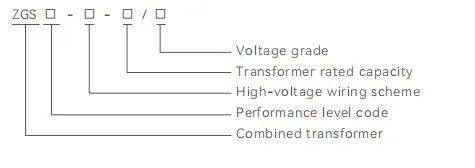
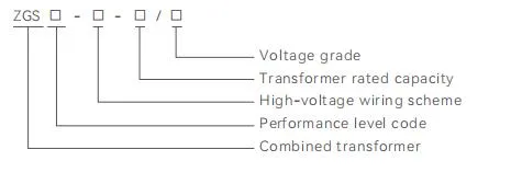
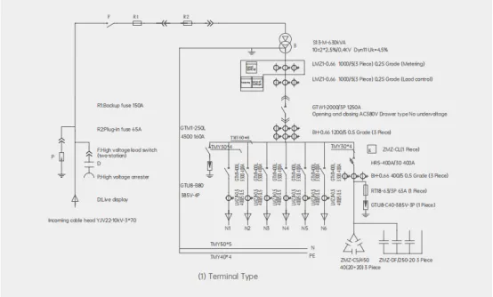
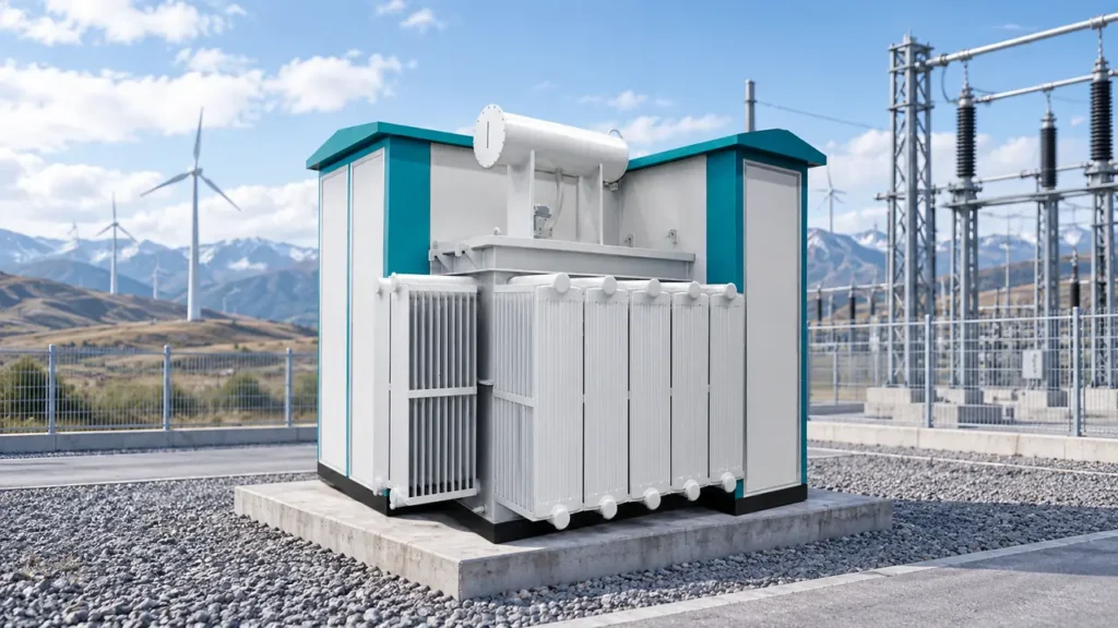
Where the approved project scope calls for an integrated transformer and MV interface, a JUBANG ZGS Combined Transformer can be discussed as equipment-family context. It should not be selected as proof of a relay scheme, CT arrangement, setting, trip matrix or protection outcome.
Fit Boundary
Use this guide to prepare and review protection-application inputs. Do not use it to set relay values, approve a coordination study, determine a mechanical-device action, authorize switching or claim compliance for a specific transformer installation.
For a project-specific discussion, contact JUBANG with the controlled input package and the named protection-design authority.
FAQs
What relays are used for transformer protection?
Schemes may combine differential, overcurrent, earth-fault, breaker-failure and monitoring functions, but the selected functions depend on transformer construction, system arrangement and the approved protection philosophy. Start with required fault coverage and interfaces rather than a fixed relay list.
What is transformer differential protection?
Differential protection compares currents associated with the protected transformer zone to identify certain internal-fault conditions. Its design depends on verified CT data, winding connections, transformer ratio and the relay application method.
Why is CT data important for transformer protection?
CT location, ratio, polarity, secondary rating and assigned protection core affect the currents presented to the relay. Incomplete or unverified CT information can invalidate the application review and site test results.
What is the difference between differential and overcurrent protection?
Differential protection is normally considered for a defined transformer zone, while overcurrent functions can provide backup and coordinate with adjacent devices for defined fault cases. The final relationship must be demonstrated in the project protection study.
When is earth-fault protection required on a transformer?
Earth-fault coverage depends on winding connection, neutral availability, grounding method, CT arrangement and the faults identified by the system study. The protection authority should confirm the required function and coordination boundary for the actual network.
What does a Buchholz relay do?
A Buchholz relay is a condition device associated with applicable oil-immersed transformer arrangements and may provide contacts for conditions related to gas accumulation or oil movement. Confirm that the device is supplied and document its intended alarm or trip action in the project logic.
Who sets transformer relay coordination?
The approved project protection authority sets the coordination approach, verifies the study cases and approves the final settings and trip logic. Equipment suppliers provide verified data, interfaces and test evidence within their documented scope.
What information is needed for a transformer protection RFQ?
Include the one-line diagram, transformer data, vector group, grounding, CT schedule, fault-study cases, operating states, protection philosophy, trip matrix, communication requirements and testing responsibilities. This allows suppliers and integrators to identify interfaces and missing data before equipment decisions are fixed.
Products are exported to more than 100 countries and regions such as Africa, the Middle East, and the United Kingdom and Europe. It is a leading manufacturer of power distribution equipment in China.

 JUBANG