From transformers and switchgear to ring main units, substations, circuit breakers and smart components, Jubang provides integrated product support for power distribution projects.
Discover Jubang’s strengths in technology R&D, quality testing and smart manufacturing, supporting reliable electrical equipment and efficient power distribution solutions for global customers.
From technical consultation and OEM/ODM customization to EPC support, smart O&M, delivery documentation and after-sales service, Jubang supports your project at every stage.
Explore Jubang Group’s development history, intelligent manufacturing base, R&D platforms, CNAS-accredited laboratory and global project service capabilities.
Why Transformer Impedance Changes Parallel Operation and Fault Duty
Release Time: 2026-07-17
Transformer impedance parallel operation must be evaluated as a network condition, not as a nameplate comparison alone. A transformer’s percent impedance is stated on a rated basis, while parallel load sharing and fault duty also depend on ratings, voltage relationship, taps, vector relationship, the upstream source, cables, and the operating state being studied.
That distinction matters before a bus tie is closed or a second transformer is specified. A lower relative impedance can take a larger share of current, and adding a parallel path can change the fault level seen by switchgear and protection. The approved system study and protection authority must confirm the final configuration.
Part 1. What does transformer impedance mean on a nameplate and in a study?
Percent impedance describes the transformer’s equivalent series impedance on its own rated voltage, rated current and MVA basis. In a short-circuit-test and per-unit base modelling context, it is a compact way to represent how the transformer limits current and contributes to voltage drop across its windings. Purdue’s distribution-system lecture uses the per-unit model for this purpose.
It is not an ohmic value that can be copied into another voltage or power base without conversion. It is also not a complete project model: the resistance and reactance components, zero-sequence behaviour where relevant, connection, source strength, and downstream path can matter to the study question.
Read with the impedance entry
Why it belongs with it
Rated MVA and winding voltages
Establish the base on which the percent value is stated
Winding arrangement and vector group
Affect the network representation and compatible parallel connection
Tap position or control state
Affects the actual voltage relationship at the common bus
R and X, or the available study model
Supports load-flow and fault-study assumptions that a magnitude alone cannot show
Test and document revision
Keeps the quotation, model and supplied transformer aligned
Before comparing two quotations, put each impedance on an explicitly stated common study basis. That is a calculation task for the appointed engineer, not a reason to publish a preferred percentage.
Part 2. What must be compatible before transformers are paralleled?
Parallel operation begins with compatible terminal voltages and phasing, not with impedance alone. The BITS Pilani parallel-operation lecture identifies voltage ratio, polarity and per-unit impedance among the conditions used to analyse a common-load arrangement.
A difference in voltage ratio or tap position can create a voltage difference at the connected terminals. The Electrical Engineering Portal discussion of transformer paralleling explains why that difference can drive circulating current even when the external load is small.
Use the following as a review list before treating a tie state as available:
confirmed primary and secondary voltage relationships at the intended tap or control positions;
compatible phase sequence, polarity, vector relationship, neutral/grounding arrangement, and bus connection;
rated MVA, percent impedance and available R/X data on stated bases;
one-line diagram, tie location, source configuration, cables and any other series elements;
proposed normal, transfer, maintenance and abnormal operating states;
switching authority, interlocks, synchronism checks where applicable, and the protection engineer’s study scope.
These items do not form a permission to close a bus tie. They define the information needed for the responsible project authority to decide whether the proposed state is suitable.
Part 3. How does impedance change load sharing?
With compatible voltage conditions, branch currents divide according to the effective impedances of the parallel paths, not according to transformer MVA labels by themselves. The BITS Pilani explanation describes current as inversely related to internal impedance and explains why equal per-unit behaviour is important when sharing should follow rating.
Consequently, a unit with lower relative impedance may reach its thermal limit while the combined bank is still below the arithmetic sum of the nameplate ratings. The actual result depends on ratings, complex impedance, tap position, load power factor, cable impedance and the connected system—not a single comparison of two percent entries.
Study question
Data to give the engineer
Decision that follows
Does each transformer stay within its permitted duty?
Transformer ratings, complex impedances, cooling/duty data and operating load cases
Allowable bank loading for each operating state
Are unwanted circulating components possible?
Actual terminal-voltage relationship, taps, vector data and network connection
Whether the proposed parallel connection is compatible
Does a cable change the apparent sharing?
Feeder routes, lengths and electrical parameters
Branch model and measurement location
Can one transformer be out of service?
Contingency state, remaining source paths and load priority
Transfer or maintenance operating plan
Do not use a generic impedance tolerance as a substitute for this model. The contract specification may state a tolerance and the factory may provide test information, but the project authority must determine whether the resulting units and system state remain acceptable together.
Part 4. Why does the parallel state change fault duty and protection coordination?
Adding a transformer branch can reduce the equivalent impedance seen from a common bus, so the prospective fault current at a given location can change. The extent of that change depends on the fault location, source contribution, transformer and cable paths, connection and sequence network, and equipment that is in or out of service.
Fault duty is more than a symmetrical-current magnitude. Protection coordination also needs the fault cases, clearing assumptions, CT behaviour, relay philosophy, breaker capability, transformer through-fault exposure and the planned switching states. IEEE C37.91 describes transformer-protection guidance that includes faults, relaying, CT behaviour, clearing and re-energization considerations.
IEEE C57.109 frames the application of overcurrent protective devices around limiting a liquid-immersed transformer’s exposure time to short-circuit current; it does not imply overload capability. CIGRE also identifies passage of short-circuit current as a severe transformer stress in its reliability paper.
Operating state to model
Why it cannot be assumed from a nameplate
One transformer in service
Establishes the base fault level and protection reach
Both transformers in parallel
May change equivalent source impedance and fault contribution
Tie open or tie closed
Can change fault paths, directional elements and selectivity
Alternate source or generator state
Changes source impedance, sequence behaviour and available duty
Faults at different bus and feeder locations
Put different equipment and relay zones under review
Protection settings and breaker application are not selected from this article. Re-run the coordinated study for the intended operating states, then issue approved settings and equipment duties through the project controls.
Part 5. What do X/R and the rest of the network change?
The same impedance magnitude can hide a different resistance/reactance split. The X/R ratio describes that split and therefore changes the angle of the impedance; it can influence current sharing, the asymmetrical fault-current context and the way source and branch contributions combine in a study.
For this reason, an impedance magnitude alone is an incomplete input when the protection or fault study requires complex and sequence data. The model should identify source impedance, transformer positive-, negative- and zero-sequence data where applicable, cable and bus impedance, grounding connection, motor or generation contribution, fault location, and equipment status.
Treat each of these as a controlled assumption:
Which source is connected and what is its available short-circuit data?
Which transformers, feeders, ties and generators are energised?
Which impedance values are measured, guaranteed, estimated or converted to the study base?
Which connection and grounding details are represented for the fault type?
Which protection elements and interrupting devices are being checked?
This is also why a fault-duty conclusion should state the study case and document revision. A conclusion from one operating state does not automatically apply after a source, cable, transformer or tie position changes.
Part 6. How are voltage regulation and losses different from fault duty?
Transformer impedance participates in voltage-drop calculations under load, while resistance is associated with load losses and reactance affects voltage behaviour with the current’s power-factor angle. Those relationships make impedance relevant to voltage regulation and losses, but they do not turn the fault-current study into a regulation calculation.
Purdue’s feeder-analysis lecture illustrates that voltage drop is evaluated from current and the series impedance of each path. A useful project review therefore keeps operating voltage, thermal loading, loss evaluation and short-circuit duty as related but distinct outputs.
Output
Typical cases
Inputs that must stay visible
Voltage regulation
Expected load and power-factor states
Transformer and feeder impedance, taps, source voltage and control mode
Load losses
Defined duty and thermal cases
Winding resistance, current, cooling and agreed loss-evaluation basis
Parallel load sharing
Common-bus operating states
Complex branch impedances, ratings, terminal voltages and path data
Fault duty
Defined faults and source states
Network equivalent, sequence data, X/R, protection and breaker locations
An apparent trade-off between voltage performance and fault limitation is a project study question. The selected transformer must satisfy the approved electrical, thermal, protection and commercial requirements together, rather than be optimised around one number.
Part 7. What should an RFQ and product discussion include?
Ask suppliers to respond to one controlled electrical specification and identify deviations rather than silently applying catalogue assumptions. The RFQ should distinguish information supplied by the owner or EPC, data confirmed by the system study, and design information proposed by the supplier.
RFQ input checklist
latest one-line diagram, common-bus arrangement, tie points and intended operating states;
transformer voltage ratio, rated MVA, vector relationship, grounding and tap-control requirements;
nameplate or proposed impedance data, stated bases, available R/X and sequence information, and applicable tolerance requirement;
source, generator, motor, cable and feeder data needed for load-flow and fault studies;
available short-circuit study, protection philosophy, CT/VT interfaces, relay responsibilities and breaker duty data;
ownership of the parallel-operation study, protection coordination, switching authorization and final acceptance decision.
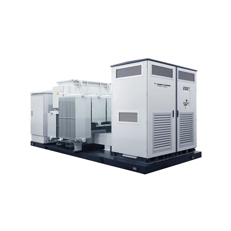
Where the approved one-line diagram supports a compact transformer-and-switchgear arrangement, discuss the JUBANG ZGS Combined Transformer as product context. This product recommendation is not a claim that a standard configuration will parallel with an existing transformer or meet a particular fault-duty requirement.
Fit Boundary
This guide fits a team preparing study inputs, an RFQ, or a review of a proposed parallel operating state. It does not replace a site-specific load-flow or short-circuit study, detailed protection coordination, switching procedure, commissioning test, or decision by the approved design authority.
For a project-specific discussion, send the one-line diagram, transformer data sheets or nameplates, intended operating states, available source and cable data, and protection responsibility split through JUBANG Contact Us.
FAQs
What is percent impedance on a transformer nameplate?
It is the transformer equivalent series impedance expressed on the transformer’s rated basis. Use the stated MVA and voltage bases when converting or comparing it in a system study.
Can transformers with different impedance operate in parallel?
Possibly, but suitability cannot be assumed. Verify voltage relationship, phasing, vector and tap compatibility, ratings, complex impedance, operating cases and protection consequences in the approved project study.
Why does the lower-impedance transformer carry more load?
With compatible terminal voltages, current tends to divide toward the lower-impedance parallel path. The actual share still depends on the complex branch impedances, transformer ratings, cables and the load condition.
Does parallel operation increase fault current?
It can change the prospective current because a second transformer path can change the network equivalent. Fault location, source contribution, cable impedance, grounding and the equipment in service determine the result.
What does X/R change in a short-circuit study?
X/R describes the resistance/reactance balance of an impedance. That balance affects impedance angle and the asymmetrical-current context, so supply the R and X data or the approved model when the study needs them.
Is transformer impedance the same as voltage regulation?
No. Impedance contributes to voltage drop under a defined load and power factor, but voltage regulation, load losses, parallel sharing and fault duty are separate calculation outputs.
Who chooses the impedance for a project?
The approved design authority determines the required configuration after considering the network, duty, protection, equipment and contract requirements. A supplier can provide design and test information, but a published article or product page cannot make that decision.
What information belongs in a transformer parallel-operation RFQ?
Include the current one-line diagram, ratings, voltage and connection data, impedance and study-base information, source and cable data, intended operating states, protection interfaces, duty cases, documentation requirements and responsibility split.
Products are exported to more than 100 countries and regions such as Africa, the Middle East, and the United Kingdom and Europe. It is a leading manufacturer of power distribution equipment in China.

 JUBANG