From transformers and switchgear to ring main units, substations, circuit breakers and smart components, Jubang provides integrated product support for power distribution projects.
Discover Jubang’s strengths in technology R&D, quality testing and smart manufacturing, supporting reliable electrical equipment and efficient power distribution solutions for global customers.
From technical consultation and OEM/ODM customization to EPC support, smart O&M, delivery documentation and after-sales service, Jubang supports your project at every stage.
Explore Jubang Group’s development history, intelligent manufacturing base, R&D platforms, CNAS-accredited laboratory and global project service capabilities.
Transformer Insulation Resistance Testing: Scope, Interpretation and Limits
Release Time: 2026-07-19
Transformer insulation resistance testing is a controlled DC diagnostic measurement of the insulation paths selected in an approved test plan. Its useful result includes the winding and ground connections, test voltage, timing, temperature, safety steps and comparable history—not only the resistance displayed by the instrument. A single IR or polarization-index result can prompt investigation, but it does not supply a universal acceptance decision or authorize energization.
Part 1. Define the scope before connecting the tester
An IR test applies DC voltage to an insulation path and observes the resulting insulation resistance. The IEEE guide for diagnostic field testing of liquid-filled transformers treats diagnostic measurements as evidence that must be interpreted together, and notes that manufacturer criteria may take precedence. That is the right starting point for a transformer test plan: define what question each measurement is intended to answer.
State the transformer construction, winding groups, terminals available, accessories connected, condition of liquid or enclosure, test owner and governing procedure. Identify whether the purpose is receiving inspection, post-installation baseline, maintenance trend, fault investigation or a prerequisite to another approved test. These purposes may require different connections, test conditions and escalation paths.
Scope item
Why it belongs in the plan
Decision owner
Transformer identity and construction
Keeps dry-type, liquid-filled and special designs from being treated as one insulation system
OEM and project engineer
Winding groups and terminal diagram
Defines the insulation paths actually being assessed
Test lead and OEM
Test purpose and governing procedure
Prevents a diagnostic spot test from being represented as acceptance
Owner and commissioning lead
Connected auxiliaries and external circuits
Identifies equipment that must be isolated or separately protected
Test lead and site electrical lead
Required comparison record
Establishes the factory, baseline or prior field data that can be meaningfully compared
Asset owner
Part 2. Read IR as a condition signal, not a verdict
IR is sensitive to the insulation system and its test condition. Moisture, surface contamination, temperature, connected accessories, leakage paths, cleanliness and the test arrangement can influence a result. The Megger transformer-testing overview also identifies temperature dependence in transformer DC insulation measurements.
That sensitivity makes a low or changed reading a reason to pause, document and investigate—not a diagnosis by itself. A high reading is also not proof that every insulation path, bushing, winding turn or dielectric mechanism is healthy. The test scope determines what was challenged; it does not silently extend to functions that the selected connection did not assess.
Reading context
What the result can support
What it cannot support alone
Comparable baseline, same arrangement and documented temperature
A trend review of the selected insulation path
A universal condition ranking
Unexpected low or unstable value
A need to check condition, setup and related evidence
A confirmed moisture mechanism or failure location
Stable value after a controlled retest
A better basis for comparison
Authorization to energize
IR combined with other approved diagnostics
A broader engineering review
Replacement of OEM or project acceptance criteria
For related site-readiness work, see oil-immersed transformer installation before energization. The installation workflow and this IR article are complementary: one organizes commissioning readiness, while the other preserves the limits of one diagnostic measurement.
Part 3. Specify winding, ground and accessory connections
The test plan should name each planned insulation path. Common categories include a selected winding group to earth, another winding group to earth, and winding-to-winding insulation. The exact sequence, winding terminals joined together, grounded windings, tank or core connection and guard arrangement must follow the transformer diagram, OEM procedure and approved project method.
Do not assume that a label such as “HV to ground” tells every test lead what to do. Record the terminal identification and whether terminals within a winding group are linked.
Also record the non-tested winding groups that are grounded and whether the tank, core, neutral, surge arrester, cable, control circuit or monitoring device remains connected. The EEP procedure overview illustrates why external circuits and accessories need to be considered before winding measurements.
Use a connection record, not a memory
Record for each measurement
Why it matters
Winding group under test
Identifies the insulation path under DC stress
Joined terminals and open links
Makes the connection repeatable
Grounded windings, tank and core
Defines the return path and prevents ambiguous comparison
Isolated cables, arresters, fans, meters and controls
Avoids measuring a parallel circuit or exposing an accessory
Guard lead, if the approved method uses one
Identifies the surface or path excluded from the measurement
Test-lead and discharge status
Supports safe handover between measurements
Before touching a lead, the transformer must be isolated, secured under the site safety system and verified de-energized. Residual charge is a hazard. Megger’s safety guidance emphasizes discharge before testing and a controlled discharge after testing; retain the earth until the authorized procedure permits its removal.
Part 4. Make voltage and timing part of the approved plan
Test voltage and test duration are not decorative fields in a result sheet. They influence the electrical stress applied and the value observed over time. The voltage must be selected for the transformer, insulation system, test objective, connected equipment and governing procedure—not copied from a generic online table.
A spot IR test and a timed measurement are different requests. State whether the plan needs a defined point-in-time reading, a sequence of timed readings, or a PI calculation. Also record the instrument model, selected range, actual applied voltage where available, start and finish times, test interruption, leakage-current indication and any automatic discharge behavior.
Test-plan input
Why it is needed
Approved DC test voltage
Confirms the selected stress matches the equipment and procedure
Reading intervals and total duration
Makes a spot result, time-resistance curve or PI calculation unambiguous
Instrument and calibration status
Preserves traceability and range limitations
Test sequence
Prevents a later measurement from being affected by an unfinished discharge or changed connection
Aborted-test rule
Defines when a reading is invalid and must be repeated under safe conditions
Use the OEM and contract procedure when they specify a voltage or timing method. If those documents conflict, resolve the responsibility before testing. An ad hoc increase in DC test voltage is not a substitute for a documented diagnostic strategy.
Part 5. Keep temperature and test history with the number
Temperature changes the insulation-resistance result. Record the winding or relevant insulation temperature, how it was measured, ambient condition, equipment state and the time since any change in operating condition. A number without its temperature and test arrangement is a weak baseline for a later comparison.
Temperature correction can help organize a trend only when the approved method, insulation system and measurement conditions support it. It does not erase differences in moisture, aging, liquid condition, surface contamination, voltage selection or test geometry. When correction uncertainty is material, a controlled retest at comparable conditions can be more informative than forcing unlike readings onto one reference temperature.
The EEP discussion of transformer diagnostics describes the complexity of transformer insulation systems and the need to interpret diagnostic results in context. Include oil or enclosure condition, humidity exposure, cleaning work, transport or maintenance event, temperature, connection record and test instrument in every baseline package.
Compare like with like
Comparison question
Record needed
Was the same insulation path measured?
Winding, ground and guard connection record
Were the test conditions alike?
Temperature, ambient, equipment state and moisture exposure
Was the same test method used?
Voltage, duration, instrument and timing intervals
Did the asset condition change?
Maintenance, transport, liquid handling, cleaning or contamination history
Is another diagnostic needed?
OEM recommendation, project procedure and related test results
Part 6. Use PI only within its transformer-specific limits
Polarization index is a timed ratio: the insulation resistance at ten minutes divided by the reading at one minute. It can describe how the measured resistance changes during a controlled DC application. That definition does not make it a universal transformer health score.
The Megger IR Q&A notes that complex oil-cellulose transformer insulation is not simple to interpret with a general-purpose insulation test.
The EEP diagnostic review similarly warns that PI can be misinterpreted for oil-cellulose systems. It identifies dielectric-response methods as a different route for quantitative moisture assessment.
Question
IR spot or timed reading
PI
What is recorded?
Resistance at stated time and conditions
Ratio of stated ten-minute and one-minute readings
What is its strongest use?
Comparable baseline or targeted check of the selected path
A test-plan-specific time-response observation
What must accompany it?
Connections, voltage, temperature and history
The same context plus insulation-system applicability
What must not be assumed?
One result defines all insulation condition
A universal threshold proves dryness or readiness
Use PI only when the OEM or approved test plan calls for it and defines its interpretation for the transformer construction. Do not transfer a ratio rule from rotating machinery or another insulation system into an oil-filled or dry-type transformer decision without that support.
Part 7. Escalate an unexpected result with related evidence
An unexpected result deserves a structured pause. First confirm safety status, test lead arrangement, discharge completion, terminal identification, isolation of external circuits, instrument setting and the recorded temperature. Then compare against the applicable factory, baseline or prior field record only after confirming that the conditions and test path are comparable.
If the value remains unexpected, bring the result to the OEM and responsible project engineers with the full test record. The next step may be an approved retest, inspection, cleaning review or moisture and liquid-condition investigation.
It may also require bushing assessment, winding-resistance or ratio evidence, dielectric-response work or another method defined by the governing procedure. The IEEE diagnostic guide supports interpreting several test results together rather than treating one measurement as conclusive.
Situation
Immediate boundary
Escalation input
Connection or isolation cannot be verified
Do not interpret the reading
Diagram, terminal photos, accessory list and OEM procedure
Temperature or equipment condition differs materially from history
Do not make a direct trend claim
Recorded conditions and approved comparison method
Value changes after a controlled retest
Do not assign a failure mechanism from IR alone
Full time record, other approved diagnostics and OEM review
PI is outside the project expectation
Do not apply a rotating-machine rule
Insulation construction, test-plan basis and relevant diagnostic evidence
An energization decision is pending
Do not use IR as authorization
Complete project acceptance package and responsible-engineer decision
Part 8. Put the decision boundary in the RFQ and test plan
An RFQ or commissioning test plan should require a result that another qualified team can repeat and interpret. Ask bidders and test providers to identify the procedure, transformer construction covered, terminal diagram, connection states, voltage, timing, temperature record, discharge and earthing method, reporting format and escalation route. Ask them to identify every assumption, exclusion and deviation before work begins.
Test purpose: receiving baseline, installation check, maintenance trend, fault investigation or approved sequence prerequisite.
Each required insulation path, including winding-to-ground and winding-to-winding configurations, plus grounded and isolated components.
Approved DC voltage, timing intervals, total duration, instrument capability, calibration evidence and aborted-test rule.
Isolation, lockout, discharge, earthing, access-control and handover responsibilities.
Temperature method, ambient and equipment condition, liquid or enclosure state, and moisture/contamination or maintenance history.
Factory records, prior comparable tests, required correction method if any, trend format and report template.
Related diagnostics, retest criteria, OEM consultation route and responsibility for any energization decision.
Fit Boundary
Use this page to specify and interpret the evidence around transformer insulation resistance testing. It does not select a test voltage, define a universal acceptance limit, publish a temperature correction factor, prove dryness, prescribe a PI limit, choose a dry-out method, replace an OEM procedure or authorize energization. Those decisions remain with the approved project specification, transformer OEM, test contractor and responsible engineering team.
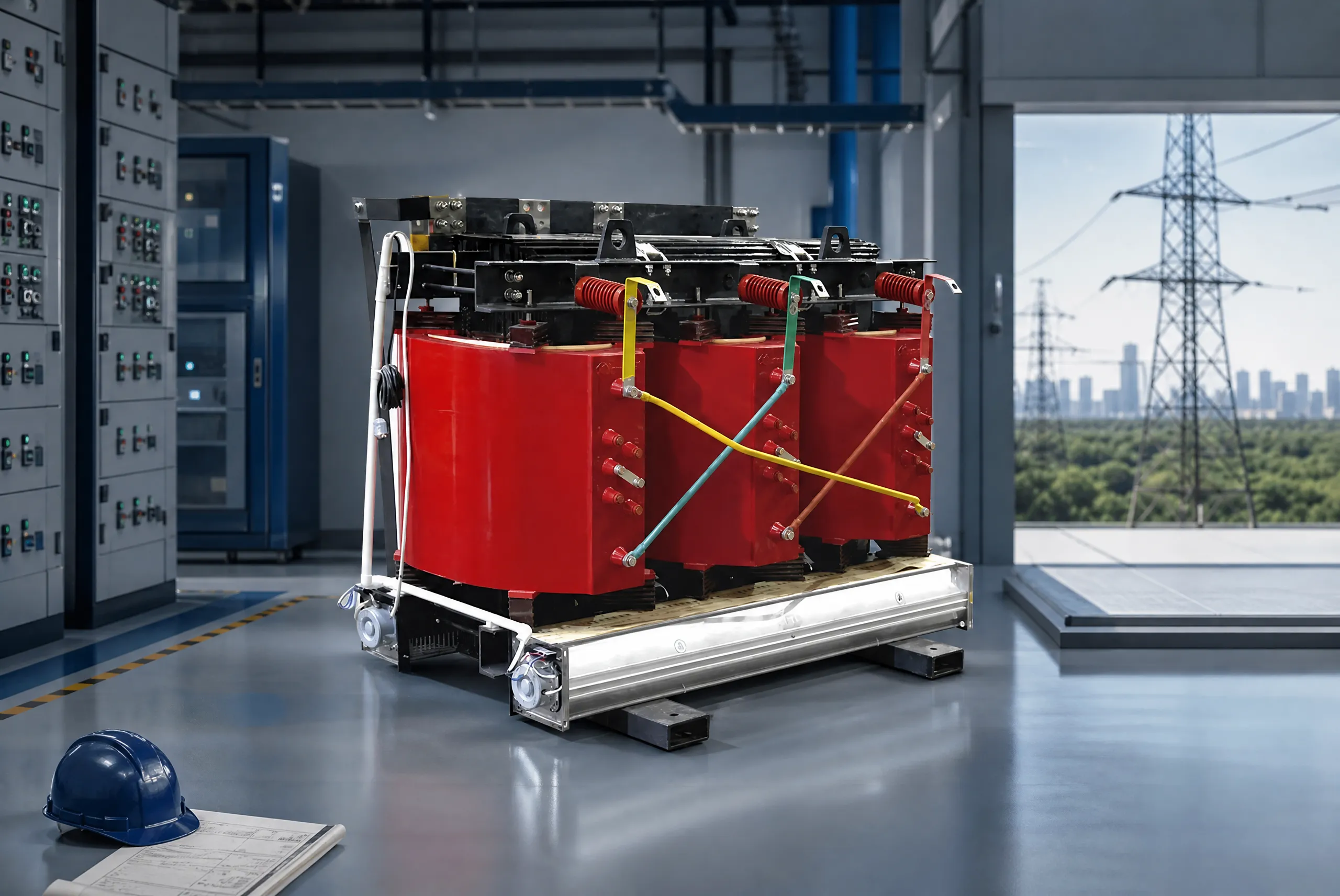
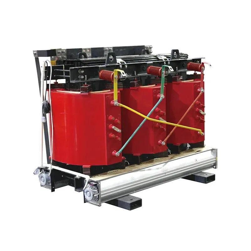
Where the approved equipment and test plan support a dry-type discussion, the JUBANG 35 kV resin-insulated dry-type transformer can be a relevant product-family starting point. It is not a conclusion about the condition, test outcome, rating, certification or suitability of a particular transformer.
Send the transformer nameplate, construction, test scope, connection diagram, OEM procedure, recorded conditions and prior comparable results to Contact JUBANG for a project-specific equipment discussion.
FAQs
What does transformer insulation resistance testing measure?
It measures the resistance of a defined insulation path while DC voltage is applied under stated conditions. The result is meaningful only with the recorded connection, voltage, timing, temperature and equipment condition.
Which connections should be included in an IR test plan?
The plan should identify each winding-to-ground and, where required, winding-to-winding path, plus every terminal joined, grounded, guarded or isolated. Use the transformer diagram and approved OEM or project procedure to define the exact arrangement.
Is winding-to-winding testing the same as winding-to-ground testing?
No. They assess different selected insulation paths and require distinct connection records. Do not infer that one arrangement automatically proves the result of another.
How should the test voltage be selected?
Select it through the approved OEM procedure, project specification, transformer construction and test objective. A generic online voltage table cannot account for connected equipment, insulation system or contractual method.
Can IR readings at different temperatures be compared?
Only with the temperature record and an approved comparison method. Temperature correction has limits, so a controlled retest at comparable conditions may be more reliable when the conditions differ materially.
Does a polarization index test prove that an oil-filled transformer is dry?
No. PI is a timed ratio, and oil-cellulose insulation can be difficult to interpret using a general-purpose ratio. Use it only when the approved transformer test plan defines its role and follow up with the appropriate evidence if results are unexpected.
What can cause a low IR result?
Possible contributors include moisture, contamination, temperature, surface condition, test connections, external circuits and equipment history. Confirm the setup and conditions first, then investigate with the OEM and approved related diagnostics.
Does a satisfactory IR result authorize energization?
No. IR is one diagnostic input. Energization requires the complete approved commissioning and acceptance decision by the responsible project parties.
What should trigger a retest or escalation?
Retest or escalate when the connection cannot be verified, conditions are not comparable, a reading is unexpected or unstable, or the result conflicts with history or other diagnostics. Preserve the full record so the next qualified reviewer can compare the same test path.
Products are exported to more than 100 countries and regions such as Africa, the Middle East, and the United Kingdom and Europe. It is a leading manufacturer of power distribution equipment in China.

 JUBANG