JUBANG



When wind EPC lead Elena Markovic in Duluth encountered a cold-start protection trip during a 35 kV collector review, she asked the team to energize the proposed package from the turbine side. The relay blocked the sequence within minutes. The reversal mattered: this was not a “bad transformer,” but a specification that had separated voltage conversion, switching duty, thermal behavior, and winter auxiliaries.
Summary: A wind power combined transformer can consolidate turbine voltage step-up, MV switching, protection interfaces, and an outdoor enclosure, but a 35 kV nameplate does not define a collector node. IEC 60076-7 guides loading assessment; IEC 60076-3 covers insulation levels and dielectric tests. Release an order only after the load and harmonic profile, fault inputs, switching-transient assumptions, low-temperature states, and FAT/SAT evidence have named owners.
What must the package coordinate beyond voltage conversion?
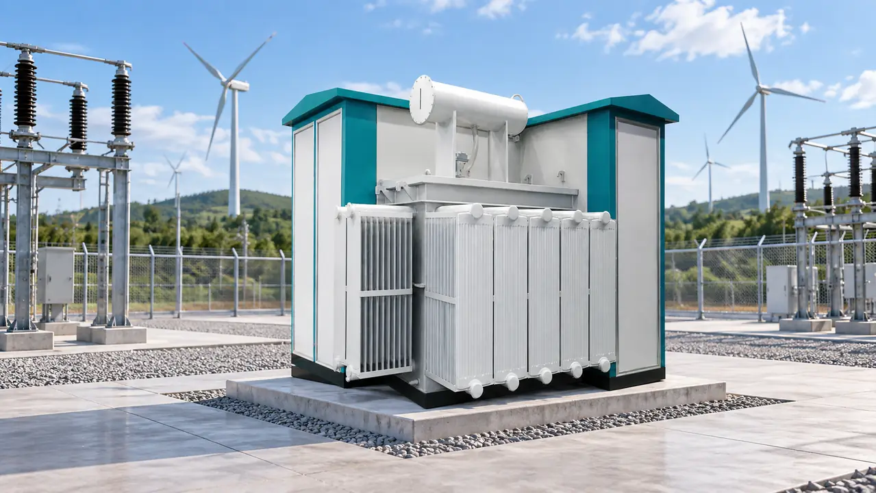
A wind farm combined step-up transformer raises turbine-side voltage to the collector-system level and may place the transformer, MV switchgear, protection and metering interfaces, surge-protection provisions, and housing in one coordinated assembly. The exact boundary varies by offer. It does not replace the plant substation or network studies; it creates a turbine or collector node whose interfaces must fit those wider systems.
Although 690 V is a frequently encountered turbine-side reference, approved turbine data governs. Buyers need system voltages, ratio and taps, vector group, impedance, grounding, insulation levels, clearances, terminations, and auxiliary supplies. Short-time and peak withstand ratings must follow the study case rather than “35 kV equipment” shorthand. IEC 60076-1 gives general transformer requirements, while IEC 62271-200 addresses metal-enclosed AC switchgear within its scope; neither alone proves site fitness.
Integration reduces some interfaces but concentrates responsibility. The single-line diagram should show the package boundary and assign relay settings, CTs/VTs, arresters, interlocks, communications, earthing, station service, and commissioning. Otherwise, compliant components can still form an uncoordinated node.
Electrical studies must start at the turbine terminals and end at the collector bus
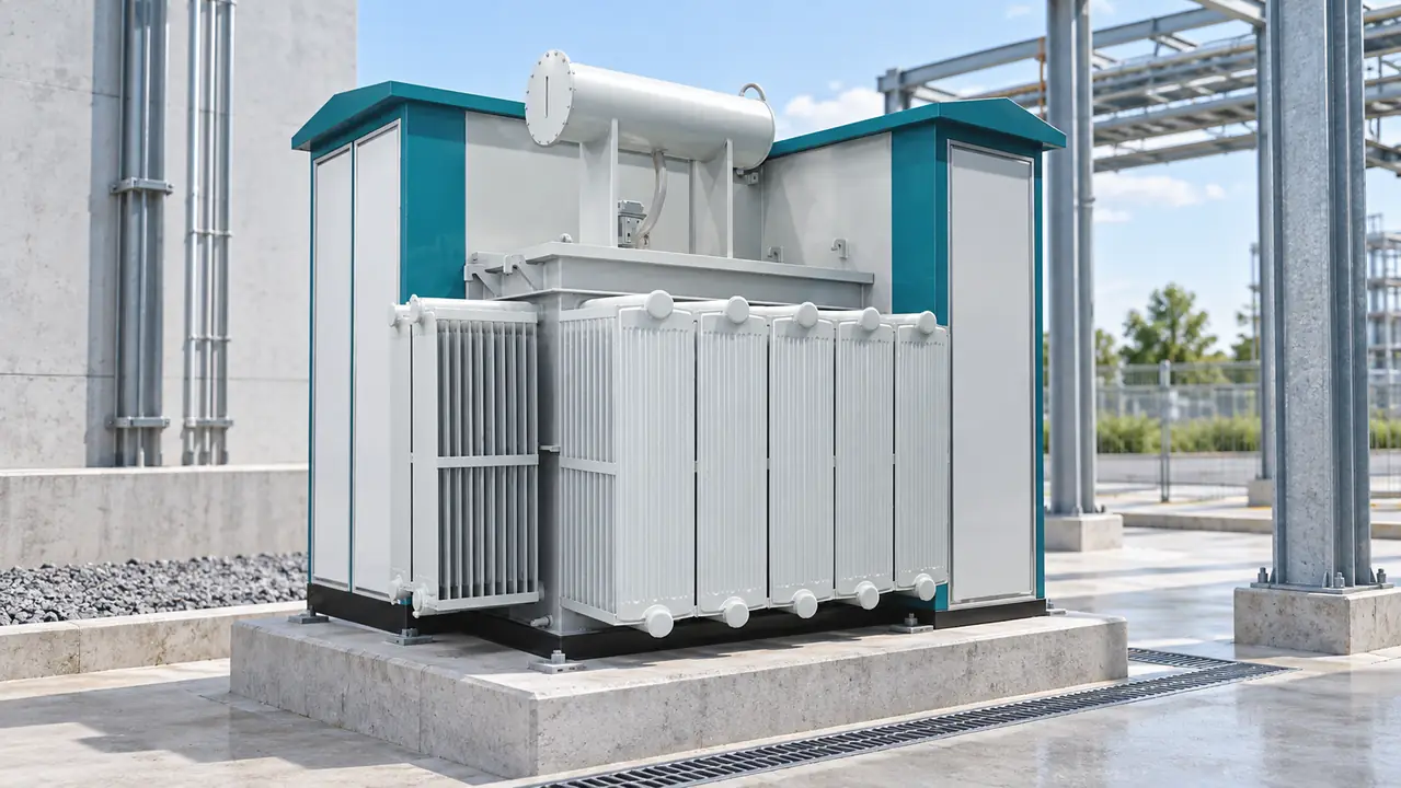
The project model should connect the turbine converter, transformer, MV switching device, collector cable, grounding system, and upstream network. Transformer impedance affects voltage regulation and fault current, but its influence cannot be judged in isolation. Feeder length and capacitance, turbine voltage-control behavior, tap selection, utility voltage limits, and operating topology belong in the same controlled study basis.
How should the project harmonic spectrum change the thermal review?
Converter-based turbines can inject harmonic currents whose magnitude varies with converter design, filters, operating point, cable network, and grid impedance. A single total harmonic distortion value does not show which frequencies drive additional winding eddy and structural stray losses. The supplier should receive a project harmonic spectrum with operating cases and should state how extra losses, hot-spot temperature, noise, and any derating were evaluated.
Wind duty also cycles repeatedly as power output and ambient conditions change. That produces alternating heating and cooling rather than one steady nameplate condition. IEC 60076-7 links load history, ambient conditions, temperatures, and insulation-ageing assessment for oil-immersed transformers; it is guidance for an engineering evaluation, not a blanket product certificate. The design review should reconcile the time-series load profile with the harmonic cases, cooling method, site temperature and altitude, temperature-rise limits, sensor locations, alarm settings, and acceptance method. This is stronger than asking whether the transformer can carry rated MVA once.
Which fault and protection inputs must be frozen before bid comparison?
Protection coordination needs maximum and minimum fault levels at the package terminals, turbine-converter fault contribution and duration, zero-sequence behavior, transformer impedance and tolerances, grounding method, collector configurations, cable data, and upstream clearing times. A converter may contribute fault current differently from a rotating machine, so an assumed generic multiple of rated current is not a safe contractual input. The responsible study party should issue the accepted model and state which operating cases set switchgear withstand, relay sensitivity, fuse or breaker coordination, and CT performance.
The RFQ should assign ownership of relay functions, trip paths, CT/VT boundaries, interlocks, communications, settings files, and change control. Maximum fault current tests withstand; minimum fault current tests whether protection will detect and clear the event. Both cases belong in the record.
Thermal cycling and cold states require separate acceptance criteria
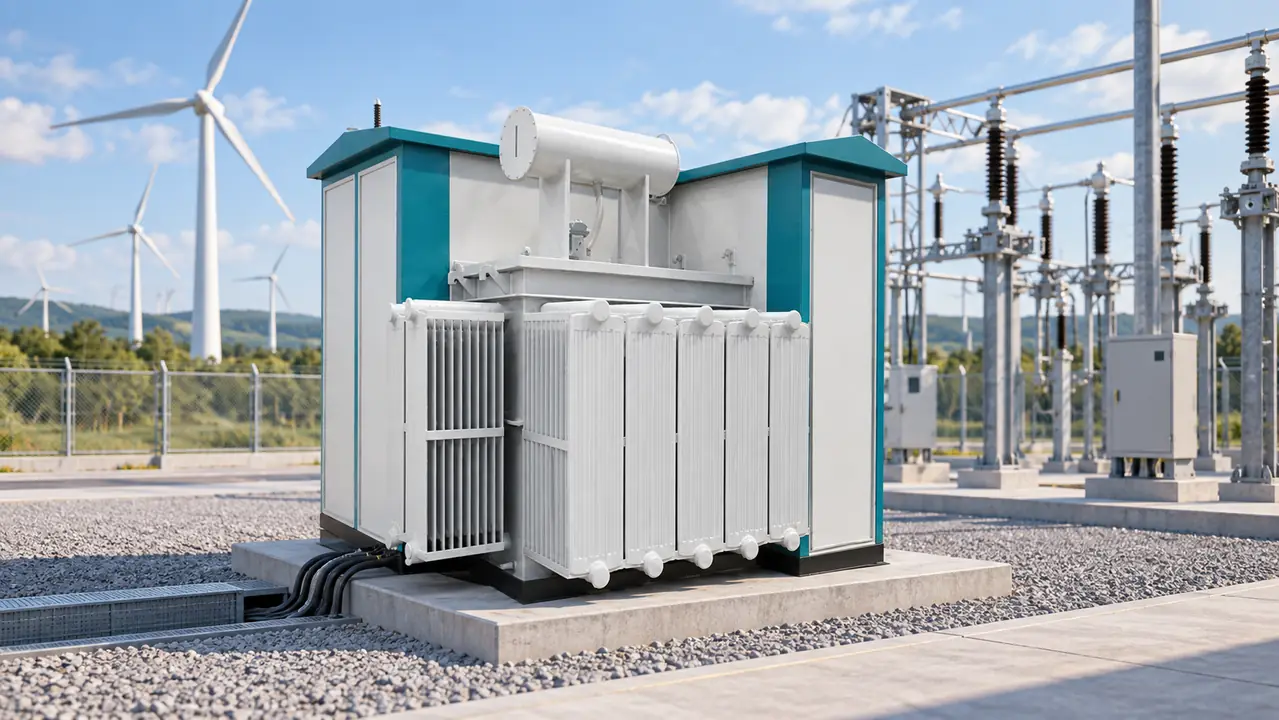
Changing wind generation creates repeated thermal cycles, while solar gain, wind exposure, and auxiliary heat alter enclosure conditions. These cycles affect insulation-ageing assessment, seals, connections, oil behavior, and moisture control even when steady-state temperature rise is acceptable. Require the duty cycle, loss basis, thermal method, cooling logic, sensors, and alarm/trip limits. Factory temperature-rise evidence must connect to project duty.
How should low-temperature requirements distinguish four different states?
“Suitable for −40 °C” is incomplete unless it identifies the state. The specification should separately define the minimum temperature for transport and storage, de-energized survival, cold energization, and normal energized operation. Each state can impose different requirements on oil viscosity or pour point, gaskets and seals, mechanisms, control batteries or DC supply, displays, relays, cable materials, and safe access.
Document heater rating and supply, humidity control, drainage or ventilation, battery autonomy, and the station-service restoration sequence. State whether heaters remain available during outages and how operators verify mechanisms and protection supplies. Low ambient temperature may aid cooling, but it does not validate cold starting or condensation control.
What does an illustrative loss calculation reveal—and what does it miss?
Assume a 2.5 MVA three-phase unit operates at 80% apparent load and 0.98 power factor. Estimated output is 2.5 × 0.80 × 0.98 = 1.96 MW. If verified no-load loss is 3 kW and load loss at rated current is 18 kW, a simplified fundamental-frequency estimate is 3 + 18 × 0.80² = 14.52 kW. This is only an illustrative screening calculation: it excludes harmonic extra losses, auxiliary consumption, temperature corrections, tap effects, tolerances, and the time distribution of operating points. Tender comparisons should use guaranteed and tested loss data with the same evaluation basis.
Choose integration only when its project value survives scrutiny
| Decision dimension | Integrated combined package | Separate transformer and MV equipment |
|---|---|---|
| Interface ownership | One assembly can reduce handoffs if responsibility is explicit. | Multiple suppliers require a detailed interface schedule. |
| Site installation | Fewer field interfaces may help; transport, foundation tolerance, and terminations still govern. | More field work, but greater freedom to position equipment. |
| Protection and transients | Early coordination can align CT/VT, arrester, cable, switch, and transformer data. | Bespoke schemes remain practical when models and settings are controlled centrally. |
| Maintenance access | A compact arrangement needs proven isolation, clearance, lifting, and replacement routes. | Equipment separation may simplify access but adds connections and space. |
| Lifecycle evaluation | May reduce civil and cabling work; package outage consequences need review. | May allow component-level replacement; interface and commissioning costs can rise. |
Integration is not automatically lower risk or lower cost. Transport limits, crane availability, foundation accuracy, cable-pulling routes, commissioning work, spares strategy, local service, loss capitalization, and outage consequences can reverse the choice. Compare whole-life cost using the same project boundary rather than comparing an integrated offer with the factory price of a transformer alone.
Your RFQ should expose every assumption that can change cost or acceptance
| Evidence group | Minimum project input | Required supplier output |
|---|---|---|
| Electrical model | Turbine converter data, load profile, harmonic spectrum, cable data, maximum and minimum fault levels | Confirmed ratio, vector group, impedance, loss data, thermal assessment, and model parameters |
| Protection and insulation | Grounding, switching device and sequence, arrester locations, insulation levels, relay philosophy | CT/VT schedule, protection responsibility, coordination inputs, terminal withstand levels, and deviations |
| Climate and auxiliaries | Four low-temperature states, altitude, contamination, wind, solar and ingress exposure | Heater load, battery/DC needs, oil and seal suitability, condensation controls, and cold-start sequence |
| Installation and service | Transport envelope, lifting restrictions, foundation tolerances, cable routes, maintenance clearances | Weights, centers of gravity, lifting plan, foundation drawing, access layout, and winter spares |
| Verification and handover | Owner witness points, grid-owner deliverables, commissioning boundaries | Drawings, data sheets, FAT/SAT scope, reports, manuals, settings baseline, spare-parts list, and as-built files |
This is a comparison baseline, not a claim that every project needs the same special tests. Distinguish design inputs, guarantees, routine tests, accepted type-test evidence, project-specific tests, and site checks. Name document approvers and deviation closeout criteria so reliability claims become auditable evidence.
Insulation coordination must link switching, cables, arresters, and transformer terminals
Wind collector systems can expose transformer terminals to switching transients shaped by the switching device, cable length and construction, grounding, surge-arrester characteristics and location, and the equipment’s terminal capacitances. A transformer dielectric level selected from nominal voltage alone does not establish coordination. IEC 60076-3 addresses insulation levels, dielectric tests, and external clearances in air for power transformers; the project insulation-coordination study must still define the stresses and protective margins for the actual arrangement.
The study basis should record rated and maximum system voltage, lightning and switching impulse requirements where applicable, cable lengths on both sides, breaker or switch technology, switching sequence, arrester model and lead length, transformer terminal data, grounding arrangement, and study responsibility. Specify whether controlled switching, surge capacitors, RC devices, or different arrester placement is required only after the analysis supports it. IEC 61400-24 provides wind-turbine lightning-protection context, but its citation does not replace the site earthing and insulation-coordination design.
Standards define scope only when the contract names the evidence
IEC 60076-1 provides general requirements for power transformers; IEC 60076-3 covers insulation levels and dielectric tests; and IEC 60076-7 supplies loading guidance for oil-immersed units. IEC 62271-202 applies to prefabricated substations within its stated scope, while IEC 62271-200 covers metal-enclosed AC switchgear. IEC 61400-24 addresses lightning protection for wind turbines. Applicability depends on the package boundary, technology, intended use, destination market, and contractual edition.
A standard can define requirements or a test method without certifying a complete product for a specific grid. List editions, test categories, factory/site responsibilities, witness points, and approval authority. Unsupported “IEC compliant” language can obscure exclusions and delay utility review when evidence does not match the supplied configuration.
A defensible selection process turns study inputs into contract deliverables
- Freeze the turbine interface, operating cases, collector topology, cable data, grounding, and voltage assumptions in controlled project documents.
- Issue the same load cycle, harmonic spectrum, fault cases, transient inputs, climate states, access constraints, and evidence schedule to every bidder.
- Normalize deviations, guaranteed losses, auxiliary consumption, test scope, exclusions, and study responsibilities before ranking commercial offers.
- Review isolation, cable access, heater supply, relay testing, lifting, oil service, winter maintenance, and replacement routes with operations personnel.
- Release manufacture only after the single-line diagram, interface schedule, design data, and agreed hold points are under document control.
This is a selection-first specification approach. At this later decision stage, wind power combined transformer configurations from Jubang Group can be reviewed against the project evidence, alongside its combined transformer range and compatible metal-clad switchgear. Ask for configuration boundaries, drawings, loss and impedance data, and agreed test responsibilities rather than relying on a family description.
Six buyer questions resolve the final transformer selection checks
What is a Wind Power Combined Transformer?
It is an integrated assembly that steps turbine-side voltage up to a wind farm’s medium-voltage collection level and coordinates transformer, switching, protection-interface, and enclosure functions. The exact component boundary varies, so confirm the single-line diagram and supplied scope instead of assuming a universal configuration.
What voltage do wind turbines use before grid connection?
Turbines commonly produce power at low voltage and use a step-up transformer for the medium-voltage collector network; 690 V is one frequently encountered turbine-side value. The actual voltage depends on the turbine and converter design. Use the approved turbine data and network study as the governing sources.
Why are combined transformers used in wind farms?
They can reduce field interfaces and coordinate transformer, switching, protection, and enclosure design in one package. Their value depends on transport, foundation, cable work, service access, losses, protection complexity, and outage strategy. Compare installed and lifecycle cost across the same scope.
How do low temperatures affect wind power transformers?
Low temperatures affect oil behavior, seals, batteries, heaters, mechanisms, controls, and maintenance access. Transport, storage, de-energized survival, cold energization, and normal operation need separate limits. Review the cold-start sequence and auxiliary-power availability before factory acceptance.
What protection equipment is integrated in a wind farm substation?
Depending on the architecture, the package may include MV breakers or switches, relays, CTs and VTs, surge-protection interfaces, interlocks, and communications. Not every item is integrated into every package. The protection philosophy, study results, and utility requirements should define the boundary.
How do you select a wind turbine step-up transformer?
Start with voltage, MVA, vector group, impedance, time-series load, harmonic spectrum, fault contribution, switching transients, climate states, and service access. Then compare guaranteed losses, thermal assessment, drawings, deviations, and FAT/SAT evidence. Select the offer whose assumptions trace cleanly into the wind farm studies and contract.
Close the decision with traceable evidence, not a nameplate
- IEC 60076-1, Power transformers—General
- IEC 60076-3, Power transformers—Insulation levels, dielectric tests and external clearances in air
- IEC 60076-7, Loading guide for mineral-oil-immersed power transformers
- IEC 62271-202, High-voltage/low-voltage prefabricated substations; and IEC 61400-24, Wind energy generation systems—Lightning protection
- Power Engineering, “Wind Farm Transformer Design Considerations” (2011)—used for stable engineering context on variable loading, harmonics, losses, voltage variation, and switching surges, not for current market statistics.
The durable lesson is simple: the package is only as dependable as the studies, interfaces, and evidence that connect it to the wind farm.
When the buying decision reaches confirmed study inputs and a controlled specification, ask Jubang Group to review the requirements for a configured wind farm step-up solution and contact discussion. Bring the single-line diagram, project profiles, fault cases, transient assumptions, and acceptance schedule so the next conversation can resolve real interfaces.