JUBANG



When a distribution engineer in Ho Chi Minh City energized a prefabricated substation, closed the 10 kV feeder and watched the low-voltage protection trip within seconds, the transformer was initially blamed. The reversal came during the drawing review: the selected Three-phase oil-immersed power transformer had the wrong vector group for the earthing arrangement, while its impedance and tap schedule did not match the switchgear study. The equipment was not defective; the specification was.
Summary: A 6-10kV Oil-immersed Power Transformer should be selected as part of a system, not from kVA alone. Confirm the actual 6, 6.3, 10 or 10.5 kV network, secondary voltage, vector group, tap range, guaranteed losses and short-circuit impedance; then require the applicable IEC 60076 tests. A 4% rather than 5% impedance, for example, can materially change fault current and voltage drop.
Why 6–10 kV transformer specifications need system context
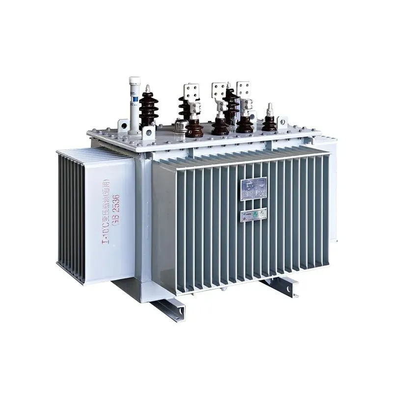
The 6–10 kV class sits between a utility or industrial medium-voltage feeder and the utilization bus, commonly 400 V but sometimes another medium-voltage level. The public product data considered here lists high-voltage options of 6, 6.3, 10 and 10.5 kV, a 0.4 kV low-voltage option, capacities from 30 to 2,500 kVA in the principal distribution table, and Dyn11, Yzn11 or Yyn0 connections. These values are a selection envelope, not a promise that every combination is interchangeable.
IEC 60076-1 establishes general requirements for power transformers, including rating, service conditions, identification and test categories. It also gives procurement teams a common vocabulary: rated power, rated voltage, tapping, connection symbol, impedance and temperature-rise basis must appear consistently across the single-line diagram, data sheet and test plan. That discipline matters because a Three-phase oil-immersed power transformer can fit physically yet remain electrically incompatible.
Rated power, voltage ratio and taps: start with the load profile
Rated power is apparent power in kVA, so the load calculation must include power factor as well as kW. For a balanced three-phase secondary, line current is approximately kVA × 1,000 ÷ (√3 × line voltage). At 0.4 kV, a 1,000 kVA unit therefore has a rated line current of about 1,443 A. That number affects the low-voltage busbar, breaker frame, cable parallel runs and enclosure heat balance; selecting the transformer in isolation pushes cost and risk downstream.
Voltage ratio should follow the declared supply and the required bus voltage under real loading. Public tabulated options show off-circuit tap ranges of ±2 × 2.5% or ±5% for relevant configurations, while separate on-load tap-changing tables show ±4 × 2.5%. A tap is not a substitute for a network study: moving a tap changes the transformation ratio, but it cannot correct inadequate kVA, excessive feeder drop or a poorly coordinated voltage-control scheme.
For a 6-10kV Oil-immersed Power Transformer, IEC 60076-1 routine measurements such as voltage ratio and phase displacement verify that the built unit matches the declared ratio and connection. Procurement documents should state the tapping type, range, step size, tapping at which losses and impedance are guaranteed, and whether operation must occur de-energized.
Vector group and neutral design: small notation, large consequence
Dyn11, Yyn0 and Yzn11 are not marketing labels. The letters describe high- and low-voltage winding connections, “n” identifies an accessible neutral, and the clock number states phase displacement in 30-degree increments. A Dyn11 transformer introduces a 30-degree displacement relative to a zero-clock reference; that difference blocks careless paralleling with Yyn0 equipment even when voltage and kVA appear equal.
Vector group also changes the zero-sequence path, neutral behavior and response to unbalanced or harmonic-rich loads. A delta high-voltage winding can provide a closed path for triplen harmonic components, while a zigzag secondary may be considered where neutral stability under imbalance is important. The correct choice still depends on the earthing study, protection philosophy and local utility rules—not on a generic preference.
IEC 60076-1 covers connection symbols and the routine check of phase displacement. Before approving a Three-phase oil-immersed power transformer, compare its guaranteed drawing with the switchgear protection settings, neutral conductor sizing and any unit intended for parallel operation. Parallel candidates require compatible ratio, polarity, phase sequence, vector group and sufficiently close impedance; otherwise circulating current or unequal load sharing can appear before nameplate capacity is reached.
Impedance, insulation and fault duty: coordinate the whole substation
Short-circuit impedance limits prospective fault current but also contributes to regulation. Ignoring upstream impedance, a simple initial estimate is rated secondary current divided by per-unit impedance: a 1,443 A transformer at 4% would imply about 36 kA, while 5% would imply about 29 kA. These figures are screening values, not final breaker duties; the actual calculation must include source strength, cables, motors and tolerances.
Published selection tables for this product family show examples of 4.0% impedance at lower ratings, 4.5% around intermediate ratings and 5.0% at larger ratings. The purchase specification must identify the guaranteed value and tolerance at the relevant tapping. IEC 60076-5 addresses the ability to withstand the thermal and dynamic effects of external short circuits, whereas IEC 60076-3 covers insulation levels, dielectric tests and external clearances in air. Neither standard turns a catalogue number into a complete project coordination study.
A 6-10kV Oil-immersed Power Transformer also needs an insulation specification aligned with the highest voltage for equipment, system earthing and destination requirements—not merely the everyday operating voltage. Ask for the lightning-impulse and power-frequency withstand levels on the guaranteed data sheet, and place the relevant routine, type or special tests in the inspection and test plan before production.
Losses, ONAN cooling and lifetime cost: evaluate energy, not slogans
No-load loss is present whenever the transformer is energized; load loss varies approximately with the square of load current at a stated reference temperature. An illustrative annual energy model is therefore: no-load kW × 8,760 hours plus load-loss kW × equivalent-load-factor-squared × energized hours. Multiplying the result by the buyer’s energy tariff and discounting over the evaluation period converts two guaranteed loss values into a comparable total-cost figure.
For example, an illustrative reduction of 0.20 kW in no-load loss saves about 1,752 kWh per continuously energized year before auxiliary or tariff adjustments. This is not a price claim or a guaranteed saving; it shows why a continuously energized but lightly loaded site may value core loss more heavily than peak efficiency. Conversely, a process plant near sustained rated load should scrutinize load loss, conductor temperature and loading cycle.
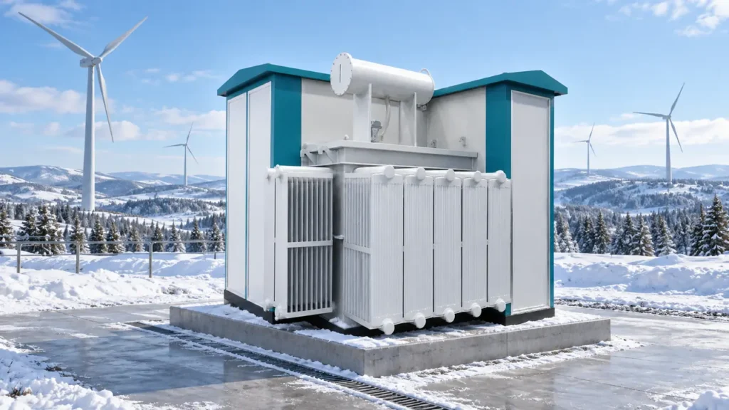
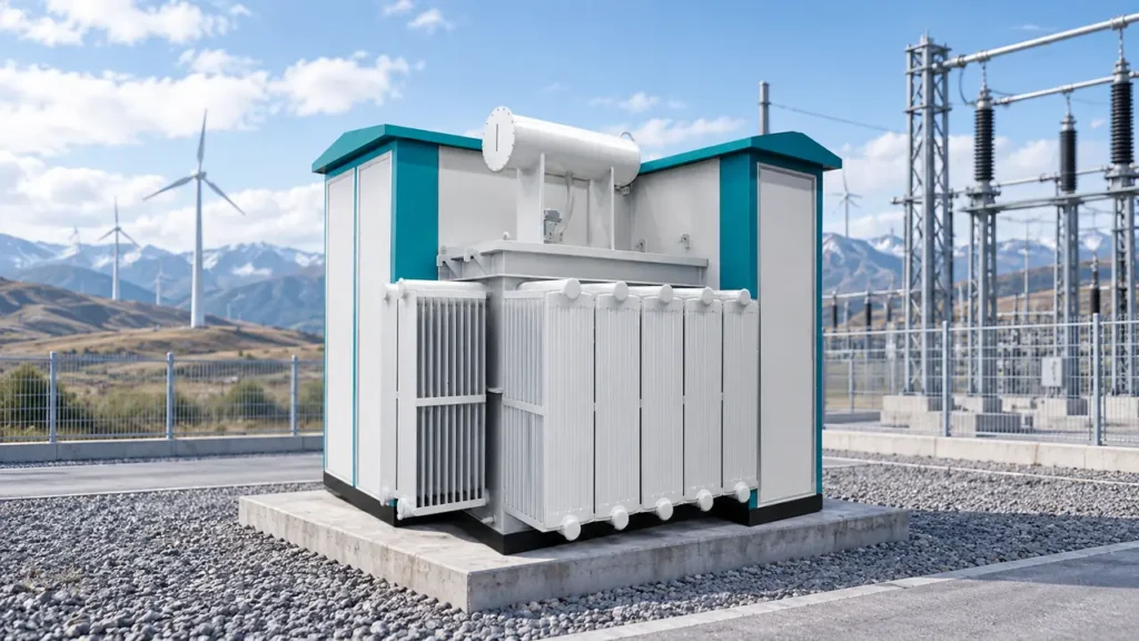
IEC 60076-2 defines temperature-rise requirements and methods for liquid-immersed transformers, while IEC 60076-7 provides a loading guide that relates load, ambient temperature, thermal behavior and insulation aging. For an ONAN-cooled Three-phase oil-immersed power transformer, radiator clearance and natural air circulation are part of the thermal system. A compact prefabricated enclosure that recirculates hot air can erase apparent footprint savings and shorten maintenance intervals.
Hidden costs include oversizing, excess switchgear fault rating, enclosure redesign, transport constraints, oil containment, outage access and rejected documentation. The lowest purchase price can therefore have the highest TCO; the defensible comparison fixes the duty cycle, evaluation years, tariff, loss capitalization method, maintenance scope and residual assumptions for every bid.
Configuration comparison for a 6-10kV Oil-immersed Power Transformer project
| Decision | Option A | Option B | Performance and TCO implication |
|---|---|---|---|
| Primary system | 6 or 6.3 kV | 10 or 10.5 kV | Match the declared network and equipment insulation level; neither option is a tap-based substitute for the other. |
| Secondary connection | Dyn11 | Yyn0 or Yzn11 | Changes phase displacement, zero-sequence behavior and parallel compatibility; protection and earthing studies decide. |
| Tap control | Off-circuit taps | On-load tap changer | Off-circuit arrangements are simpler; on-load regulation adds control capability, maintenance points and specification complexity. |
| Impedance | Lower percentage | Higher percentage | Lower impedance improves regulation but raises prospective fault current; higher impedance does the reverse. |
| Loss evaluation | Lower no-load loss emphasis | Lower load loss emphasis | Choose using energized hours and load profile, not a single “efficient” label. |
| Voltage class alternative | 6-10kV Oil-immersed Power Transformer | 35 kV class transformer | Use the project’s actual incoming voltage; moving classes changes insulation, footprint and upstream equipment. |
Application matrix: where the selection priorities change
| Application | Dominant duty | Specification priorities | Common mismatch to prevent |
|---|---|---|---|
| Prefabricated substation | Restricted ventilation and access | Footprint, ONAN airflow, cable orientation, oil containment, sound | Accepting a transformer drawing before checking enclosure heat paths |
| MV switchgear-to-LV board package | High secondary fault level | Impedance, breaker duty, busbar current, protection coordination | Changing impedance after switchgear ratings are frozen |
| Industrial process plant | Motors, harmonics and continuous load | Starting drop, load loss, harmonic study, thermal margin | Using connected kW without diversity, power factor or starting current |
| Commercial or infrastructure campus | Variable daily load | No-load loss, maintainability, noise, future expansion | Oversizing every unit and paying continuous core-loss penalties |
| Renewable-energy auxiliary system | Variable generation and bidirectional scenarios | Voltage range, protection directionality, loading cycle, utility rules | Assuming a distribution data sheet automatically covers reverse power |
Standards and compliance checkpoints
- IEC 60076-1: general requirements, ratings, markings and test categories. Specify edition and project deviations.
- IEC 60076-2: temperature-rise requirements and test methods for liquid-immersed transformers.
- IEC 60076-3: insulation levels, dielectric tests and external clearances in air.
- IEC 60076-5: ability to withstand external short circuits; it does not replace the project fault study.
- IEC 60076-7: loading guidance for oil-immersed transformers; use it with the actual ambient and duty cycle.
- IEC 60076-10: determination of sound levels; agree measurement conditions and guaranteed values when noise matters.
These are standards and test methods, not blanket product certifications. CE marking, CB reports or KEMA-related claims—if relevant to a destination—must be checked against the exact model, document issuer, scope and market rule. Unsupported or out-of-scope claims can delay technical approval, customs documentation or energization, so buyers should request traceable reports rather than rely on a logo.
Four procurement actions before approving the data sheet
Jubang Group can discuss configurable three-phase oil-immersed power transformer ratings, connections, losses and documentation, but the buyer should first turn the system study into an auditable schedule. Use these actions:
- Freeze interfaces. Record normal and maximum system voltage, frequency, required secondary voltage, earthing method, phase sequence, cable entry, enclosure constraints and ambient conditions.
- Issue a loss and impedance schedule. State guaranteed no-load loss, load loss reference temperature, impedance and tolerances; evaluate the Three-phase oil-immersed power transformer against one documented TCO formula.
- Cross-check alternatives deliberately. If the feeder is genuinely 35 kV, review the 35 kV oil-immersed transformer range. If low no-load loss and compact magnetic design are priorities, assess the three-dimensional wound-core option without assuming it fits every duty.
- Make evidence part of the order. Define routine, type and special tests; request drawings, nameplate data and test records for the offered model, and review the supplier’s public qualification and certification information only within its stated scope.
Frequently asked questions
What is a 6-10kV Oil-immersed Power Transformer used for?
It steps a 6, 6.3, 10 or 10.5 kV distribution supply to a lower voltage for industrial plants, buildings, infrastructure or packaged substations. The exact application depends on the secondary voltage, kVA, vector group, impedance, cooling arrangement and local grid rules.
How do I size a Three-phase oil-immersed power transformer?
Convert the diversified peak demand to kVA, account for power factor, motor starting, harmonics, ambient temperature and credible growth, then compare the loading cycle with IEC 60076-7 guidance. Avoid adding unrelated contingency factors repeatedly, because chronic oversizing raises capital cost and annual no-load energy.
Is Dyn11 always better than Yyn0?
No. Dyn11 offers a neutral on the star-connected secondary and a delta path on the primary, but it also introduces a 30-degree displacement. Yyn0 has different zero-sequence and paralleling implications; the earthing, protection, harmonic and parallel-operation studies should decide.
Why does transformer impedance matter to switchgear selection?
Percentage impedance helps determine transformer-limited fault current and voltage drop. A lower value can improve regulation but may require higher breaker and busbar withstand ratings; use the guaranteed impedance and tolerance in the complete IEC 60909 or applicable local fault calculation.
Which tests should be requested for a 6-10kV Oil-immersed Power Transformer?
At minimum, align the order with the applicable IEC 60076 routine tests, including winding resistance, ratio and phase displacement, short-circuit impedance and load loss, no-load loss and current, and dielectric testing. Type or special tests—such as temperature rise, impulse, sound or short-circuit evidence—should be specified according to project risk and prior valid test evidence.
Authoritative references
- IEC 60076-2:2011 — Temperature rise for liquid-immersed transformers
- IEC 60076-3:2013 — Insulation levels, dielectric tests and clearances
- IEC 60076-5:2006 — Ability to withstand short circuit
- IEC 60076-7:2005 — Loading guide for oil-immersed power transformers
The memorable rule is simple: the transformer nameplate closes the selection process; it should never start it.
For a project-specific review of ratings, vector group, impedance, losses and test documentation, compare your single-line diagram and load schedule with the 6-10kV Oil-immersed Power Transformer range and contact Jubang Group with the destination-market requirements.