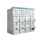
KYN28A-12 Metal Clad Switchgear
KYN28A-12 Metal clad switchgear (hereinafter referred to as switchgear) is suitable for...
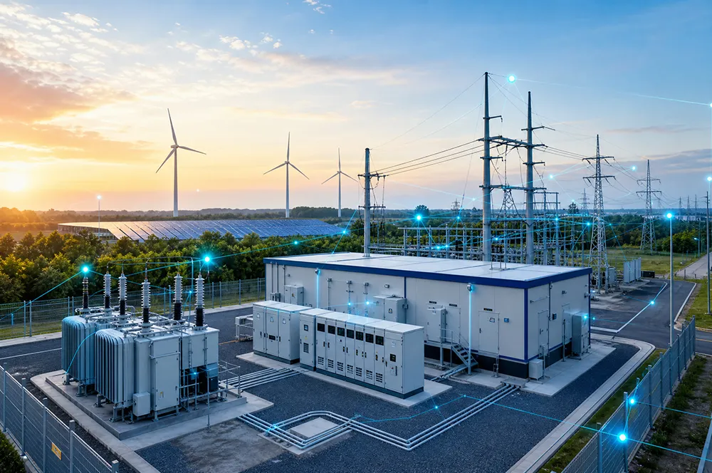
From transformers and switchgear to ring main units, substations, circuit breakers and smart components, Jubang provides integrated product support for power distribution projects.
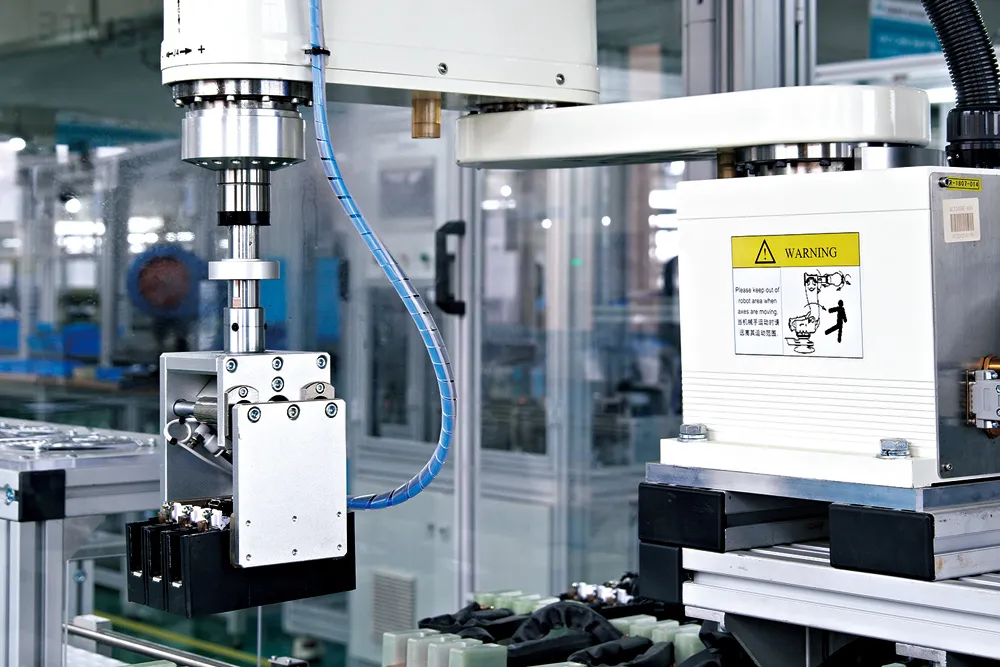
Discover Jubang’s strengths in technology R&D, quality testing and smart manufacturing, supporting reliable electrical equipment and efficient power distribution solutions for global customers.
From technical consultation and OEM/ODM customization to EPC support, smart O&M, delivery documentation and after-sales service, Jubang supports your project at every stage.
Explore Jubang Group’s development history, intelligent manufacturing base, R&D platforms, CNAS-accredited laboratory and global project service capabilities.

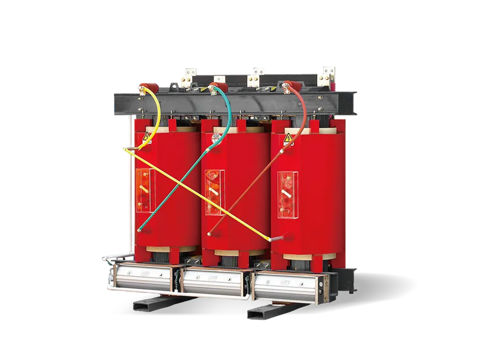
High Sealing Performance
Energy Saving & Reduced Loss
Low Noise
Compact Structure
Technical Data – 35kV S11 Series Oil-Immersed Three-Phase Distribution Transformer
| Rated Capacity(kVA) | Voltage Combination(kV) | Vector Group | Loss(kW) | No-load Current(%) | Short-circuit Impedance(%) | Weight(kg) | Overall Dimensions(mm) L×W×H |
Track Gauge(Longitudinal/Transverse) | |||||
| HV | HV Tapping Range(%) | LV | No-load | Load Loss | Active Part Weight | Oil Weight | Total Weight | ||||||
| 30 | 35 38.5 |
±2×2.5 ±5 |
0.4 | Dyn11 Yyn0 |
0.14 | 0.89/0.84 | 1.7 | 4.0 | 165 | 230 | 580 | 1320×550×1550 | 550/400 |
| 50 | 0.16 | 1.20/1.14 | 1.3 | 230 | 265 | 730 | 1360×700×1680 | ||||||
| 80 | 0.22 | 1.80/1.71 | 1.1 | 310 | 310 | 870 | 1395×730×1730 | ||||||
| 100 | 0.23 | 2.01/1.91 | 1.1 | 370 | 340 | 1000 | 1440×760×1810 | ||||||
| 125 | 0.27 | 2.37/2.26 | 1.0 | 440 | 380 | 1120 | 1450×800×1940 | 660/660 | |||||
| 160 | 0.28 | 2.82/2.68 | 1.0 | 540 | 415 | 1360 | 1470×800×2910 | ||||||
| 200 | 0.34 | 3.32/3.16 | 1.0 | 635 | 455 | 1540 | 1500×800×2050 | ||||||
| 250 | 0.40 | 3.95/3.76 | 0.95 | 725 | 490 | 1745 | 1530×830×2090 | ||||||
| 315 | 0.48 | 4.75/4.53 | 0.95 | 825 | 525 | 1910 | 1550×870×2150 | ||||||
| 400 | 0.58 | 5.74/5.47 | 0.85 | 980 | 595 | 2220 | 1600×940×2200 | 660/660 | |||||
| 500 | 0.68 | 6.91/6.58 | 0.85 | 1210 | 680 | 2640 | 1750×1000×2280 | ||||||
| 630 | 0.83 | 7.86 | 0.65 | 1110 | 800 | 3175 | 2130×950×2400 | ||||||
| 800 | 0.98 | 9.40 | 0.65 | 1625 | 850 | 3595 | 2210×1075×2450 | ||||||
| 1000 | 1.15 | 11.50 | 0.65 | 1955 | 965 | 4260 | 2250×1090×2630 | ||||||
| 1250 | 1.40 | 13.90 | 0.6 | 2250 | 1130 | 4835 | 2210×1740×2690 | 1070/1070 | |||||
| 1600 | 1.69 | 16.60 | 0.6 | 2890 | 1260 | 5995 | 2250×2145×2700 | ||||||
| 2000 | 1.99 | 19.7 | 0.55 | 3070 | 1330 | 6445 | 2320×2170×2750 | ||||||
| 2500 | 2.36 | 23.2 | 0.55 | 3555 | 1390 | 7080 | 2340×2180×2510 | ||||||
Notes:
① For transformers ≤500 kVA, load loss above the diagonal line applies to Dyn11, and load loss below the diagonal line applies to Yyn0.
② Dimensions are for reference only; final dimensions are subject to the approved outline drawing
| Rated Capacity(kVA) | Voltage Combination(kV) | Vector Group | Loss(kW) | No-load Current(%) | Short-circuit Impedance(%) | Weight(kg) | Overall Dimensions(mm) L×W×H |
Track Gauge(Longitudinal/Transverse) | |||||
| HV | HV Tapping Range(%) | LV | No-load | Load Loss | Active Part Weight | Oil Weight | Total Weight | ||||||
| 200 | 35 | ±2×2.5 ±5 |
3.15 6.3 10.5 |
Yd11 | 0.34 | 3.16 | 1.2 | 6.5 | 670 | 405 | 1445 | 1240×1270×1700 | 660/660 |
| 250 | 0.41 | 3.75 | 1.1 | 735 | 410 | 1550 | 1290×1280×1810 | ||||||
| 315 | 0.49 | 4.53 | 1.1 | 910 | 485 | 1855 | 1300×1350×1960 | ||||||
| 400 | 0.58 | 5.47 | 1.0 | 1015 | 585 | 2000 | 2020×940×1990 | 820/820 | |||||
| 500 | 0.69 | 6.58 | 1.0 | 1225 | 675 | 2460 | 2150×1000×2040 | ||||||
| 630 | 0.83 | 7.86 | 0.65 | 1335 | 695 | 2665 | 2260×1060×2050 | ||||||
| 800 | 0.98 | 9.40 | 0.65 | 1695 | 825 | 3355 | 2330×1080×2130 | ||||||
| 1000 | 1.15 | 11.50 | 0.65 | 1975 | 920 | 3785 | 2390×1100×2190 | ||||||
| 1250 | 1.40 | 13.90 | 0.55 | 2155 | 990 | 4250 | 2450×1210×2210 | ||||||
| 1600 | 1.69 | 16.60 | 0.45 | 2505 | 1120 | 4995 | 2475×1230×2420 | 1070/1070 | |||||
| 2000 | 2.17 | 18.30 | 0.45 | 2815 | 1155 | 5460 | 2380×2010×2430 | ||||||
| 2500 | 2.56 | 19.60 | 0.45 | 3730 | 1370 | 6305 | 2460×2150×2520 | ||||||
| 3150 | 35 38.5 |
3.04 | 23.00 | 0.45 | 7.0 | 4165 | 1650 | 8360 | 2550×2220×2540 | ||||
| 4000 | 3.62 | 27.30 | 0.45 | 5160 | 1970 | 9350 | 2670×2390×2630 | ||||||
| 5000 | 4.32 | 31.30 | 0.45 | 6130 | 2215 | 10770 | 2870×2450×2930 | ||||||
| 6300 | 5.24 | 35.00 | 0.45 | 8.0 | 8120 | 2705 | 13885 | 3100×2580×3070 | 1475/1475 | ||||
| 8000 | 35 38.5 |
±2×2.5 | 3.15 3.3 6.3 6.6 10.5 |
Ynd11 | 7.20 | 38.40 | 0.35 | 9760 | 2915 | 15510 | 3250×2680×3270 | ||
| 10000 | 8.70 | 45.30 | 0.35 | 11025 | 3225 | 18150 | 3320×2720×3350 | ||||||
| 12500 | 10.00 | 53.80 | 0.30 | 14170 | 4085 | 21760 | 3410×2950×3530 | ||||||
| 16000 | 12.10 | 65.80 | 0.30 | 17735 | 4710 | 26350 | 3520×3180×3690 | ||||||
| 20000 | 14.40 | 79.50 | 0.30 | 20430 | 5755 | 32560 | 3730×3560×4110 | ||||||
| 25000 | 17.00 | 94.00 | 0.25 | 10.0 | 25265 | 7010 | 38885 | 4110×4120×4340 | 2040/2040 | ||||
| 31500 | 20.20 | 112.0 | 0.25 | 30360 | 8515 | 46090 | 4760×4570×4510 | ||||||
Notes:
① For transformers with LV=10.5 kV, the Dyn11 vector group is available.
② Dimensions are for reference only; final dimensions are subject to the approved outline drawing.
| Rated Capacity(kVA) | Voltage Combination(kV) | Vector Group | Loss(kW) | No-load Current(%) | Short-circuit Impedance(%) | Weight(kg) | Overall Dimensions(mm) L×W×H |
Track Gauge(Longitudinal/Transverse) | |||||
| HV | HV Tapping Range(%) | LV | No-load | Load Loss | Active Part Weight | Oil Weight | Total Weight | ||||||
| 800 | 35 | ±3×2.5 | 6.3 10.5 |
Yd11 | 1.25 | 9.88 | 0.9 | 6.5 | 1735 | 995 | 3625 | 2790×1220×2130 | 820/820 |
| 1000 | 1.50 | 12.16 | 0.9 | 2015 | 1105 | 4055 | 2830×1240×2150 | ||||||
| 1250 | 1.77 | 14.63 | 0.81 | 2190 | 1155 | 4580 | 2870×1310×2210 | ||||||
| 1600 | 2.16 | 17.48 | 0.77 | 2535 | 1295 | 5245 | 2875×1310×2380 | ||||||
| 2000 | 2.30 | 19.20 | 0.50 | 2855 | 1345 | 5935 | 2980×2880×2380 | 1070/1070 | |||||
| 2500 | 2.72 | 20.60 | 0.50 | 3815 | 1575 | 6745 | 3060×2190×2490 | ||||||
| 3150 | 35 38.5 |
3.23 | 24.70 | 0.50 | 7.0 | 4235 | 1860 | 8780 | 3180×2240×2510 | ||||
| 4000 | 3.87 | 29.10 | 0.50 | 5230 | 2260 | 9820 | 3270×2410×2600 | ||||||
| 5000 | 4.64 | 34.20 | 0.50 | 6195 | 2545 | 11510 | 3490×2480×2840 | ||||||
| 6300 | 5.63 | 36.70 | 0.50 | 8315 | 3095 | 14805 | 3710×2600×3005 | 1475/1475 | |||||
| 8000 | 6.3 6.6 10.5 |
Ynd11 | 7.87 | 40.60 | 0.40 | 7.5/8.0 | 9870 | 3480 | 16590 | 3850×2680×3230 | |||
| 10000 | 9.28 | 48.00 | 0.40 | 11025 | 4160 | 19930 | 3960×2750×3310 | ||||||
| 12500 | 10.0 | 56.80 | 0.35 | 14270 | 5265 | 24295 | 4035×2980×3530 | ||||||
| 16000 | 13.1 | 70.30 | 0.35 | 17780 | 6280 | 28720 | 4140×3200×3660 | ||||||
| 20000 | 15.5 | 82.70 | 0.30 | 20205 | 7415 | 37380 | 4070×3580×4170 | ||||||
| 25000 | 18.3 | 97.8 | 0.30 | 10.0 | 24950 | 9030 | 43425 | 4710×4120×4310 | 2040/2040 | ||||
| 31500 | 21.8 | 116.00 | 0.30 | 29820 | 11025 | 51555 | 5360×4570×4450 | ||||||
Notes:
① For transformers with LV=10.5 kV, the Dyn11 vector group is available.
② The maximum current tap is at the -7.5% position.
③ Dimensions are for reference only; final dimensions are subject to the approved outline drawing.


