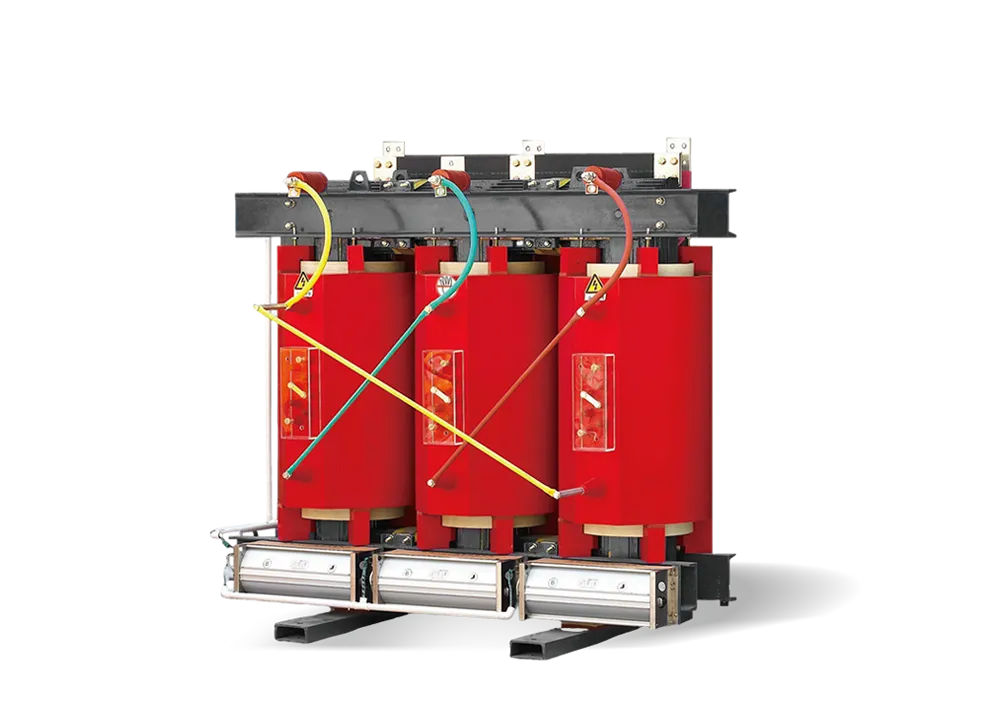
6-10kV SCB Resin-Insulated Dry-Type Transformer
Optimized Magnetic Circuit Energy Saving & Reduced Loss Low Noise Strong Overload...
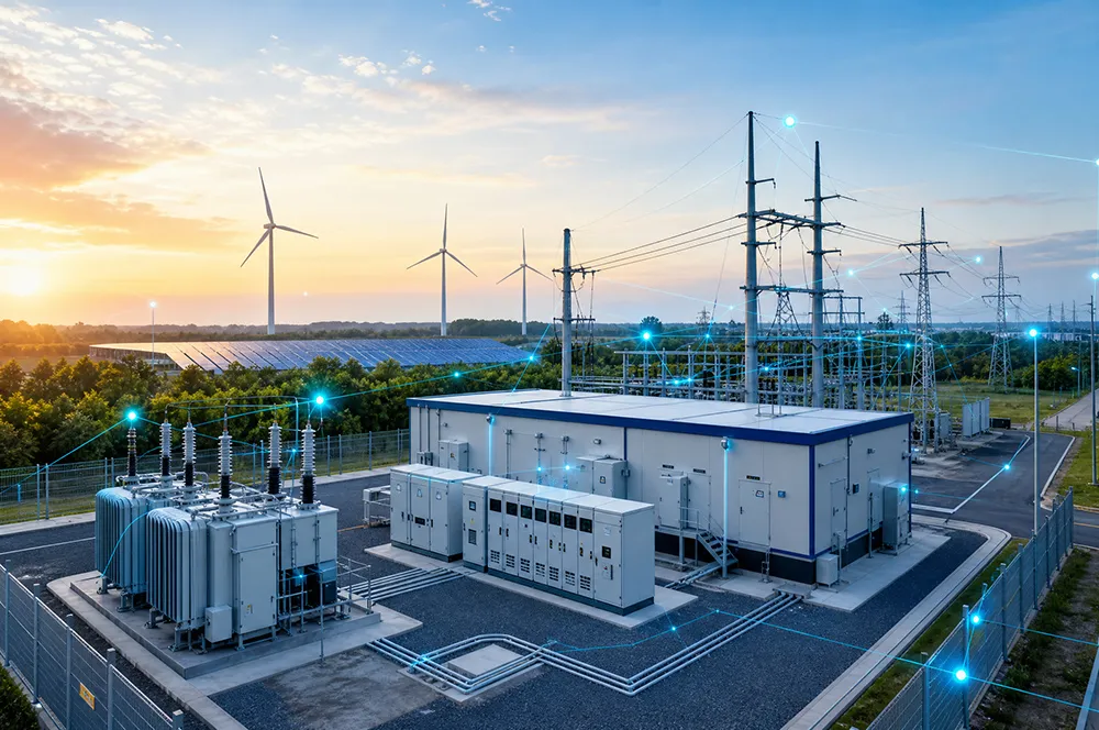
From transformers and switchgear to ring main units, substations, circuit breakers and smart components, Jubang provides integrated product support for power distribution projects.
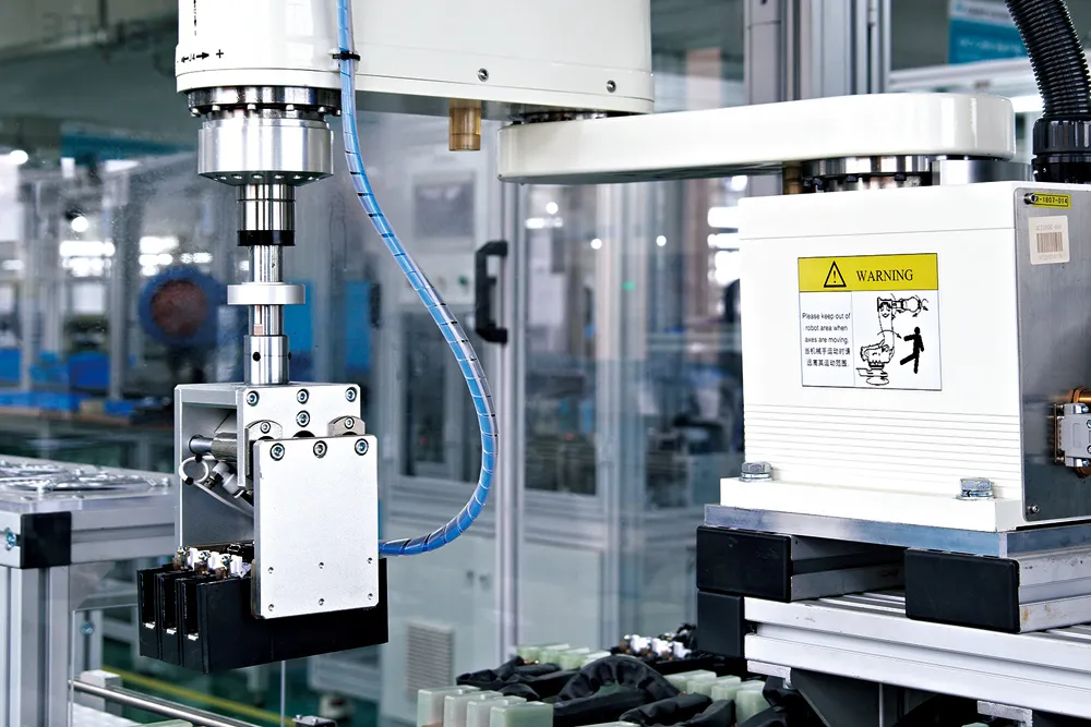
Discover Jubang’s strengths in technology R&D, quality testing and smart manufacturing, supporting reliable electrical equipment and efficient power distribution solutions for global customers.
From technical consultation and OEM/ODM customization to EPC support, smart O&M, delivery documentation and after-sales service, Jubang supports your project at every stage.
Explore Jubang Group’s development history, intelligent manufacturing base, R&D platforms, CNAS-accredited laboratory and global project service capabilities.

Optimized Magnetic Circuit
Energy Saving & Reduced Loss
Low Noise
Strong Overload Capability
Compact Structure
The three-dimensional wound core transformer is a high-efficiency and energy-saving power transformer. It innovatively replaces the traditional laminated core structure and three-phase layout used in conventional transformers, resulting in optimized performance. With a fully symmetrical three-phase magnetic circuit, the transformer achieves significant energy-saving performance, greatly reduced noise, improved heat dissipation capability, stronger overload capacity, and a compact structure.
① The three-dimensional wound core has no joints, ensuring uniform magnetic distribution throughout the magnetic circuit without obvious high-flux regions or sudden changes in magnetic flux density caused by joints.
② The magnetic flux direction is fully consistent with the grain orientation of the silicon steel sheet.
③ The three-phase magnetic path lengths are completely equal, achieving the shortest possible magnetic circuit.
④ The three-phase magnetic circuits are perfectly symmetrical, resulting in fully balanced three-phase no-load currents.
① The magnetic flux direction of the three-dimensional wound core is completely consistent with the rolling direction of the silicon steel sheet. In addition, the core layers are continuously wound without overlapping joints, resulting in uniform magnetic flux distribution without obvious high-flux regions or sudden flux density changes. Under the same material conditions, compared with traditional laminated cores, the core process coefficient is reduced from 1.3-1.5 to about 1.05, which alone can reduce core loss by 10-20%.
② Due to the special three-dimensional structure, the core weight is reduced by about 25% compared with traditional laminated cores, and the corner weight accounts for about 6% of the total core weight.
③ After shearing, the silicon steel sheets undergo magnetic property annealing treatment. The three-dimensional wound core is subjected to high-temperature (about 800℃) vacuum annealing, which eliminates internal stress and refines the magnetic domains of the silicon steel sheet, significantly improving its magnetic properties.
④ Test results show that the no-load loss of the three-dimensional wound core transformer can be reduced by 25-35% compared with national standards, and the no-load current can be reduced by up to 92%.
The three-dimensional wound core is manufactured by continuously winding silicon steel strips on a dedicated core winding machine, forming a compact structure without joints. This eliminates noise caused by discontinuous magnetic circuits commonly found in laminated cores.
At the same time, the three-phase magnetic circuit is symmetrical and the operating magnetic density is properly designed, which significantly reduces transformer noise.
According to tests, the noise level of the transformer can be as low as 47 dB, which is 19 dB lower than the standard limit of 66 dB, approaching environmental silence standards and making it particularly suitable for indoor installations and residential areas.
① The transformer itself generates very little heat. The no-load loss and no-load current of the wound core transformer are extremely low, resulting in minimal heat generation during operation.
② The three-phase windings are arranged in a “品”-shaped configuration. A natural ventilation channel-known as the chimney effect-is formed in the center of the windings. As the iron core heats up to approximately 30-40℃, air is heated and rises naturally. Cooler air is drawn in from the lower central channel, and heat is dissipated outward from the iron core, enabling natural circulation and rapid heat removal from the transformer.
The special three-dimensional wound core structure results in a compact and well-organized layout.
The plan area of the transformer body is reduced by about 10-15% compared with conventional
transformers.
The overall height is reduced by approximately 10-20%
When installed in a box-type substation, the enclosure volume can be reduced by about one quarter.
Main Technical Parameters of 6kV/10kV S13-M.RL Series Grade 3 Energy-Efficient Three-Dimensional Wound Core Off-Circuit Tap-Changing Transformers
| Rated Capacity(kVA) | Voltage Combination & Tapping Range | Vector Group | No-load Loss(W) | Load Loss(W) | Short-circuit Impedance(%) | No-load Current(%) | ||
| HV(kV) | HV Tapping Range(%) | LV(kV) | ||||||
| 30 | 6 6.3 10 10.5 11 |
±2×2.5 ±5 |
0.4 | Dyn11 Yzn11 Yyn0 |
80 | 630/600 | 4 | 0.3 |
| 50 | 100 | 910/870 | 4 | 0.24 | ||||
| 63 | 110 | 1090/1040 | 4 | 0.23 | ||||
| 80 | 130 | 1310/1250 | 4 | 0.22 | ||||
| 100 | 150 | 1580/1500 | 4 | 0.21 | ||||
| 125 | 170 | 1890/1800 | 4 | 0.2 | ||||
| 160 | 200 | 2310/2200 | 4 | 0.19 | ||||
| 200 | 240 | 2730/2600 | 4 | 0.18 | ||||
| 250 | 290 | 3200/3050 | 4 | 0.17 | ||||
| 315 | 340 | 3830/3650 | 4 | 0.16 | ||||
| 400 | 410 | 4520/4300 | 4 | 0.16 | ||||
| 500 | Dyn11 Yyn0 |
480 | 5410/5150 | 4 | 0.16 | |||
| 630 | 570 | 6200 | 4.5 | 0.15 | ||||
| 800 | 700 | 7500 | 4.5 | 0.15 | ||||
| 1000 | 830 | 10300 | 4.5 | 0.14 | ||||
| 1250 | 970 | 12000 | 4.5 | 0.13 | ||||
| 1600 | 1170 | 14500 | 4.5 | |||||
Main Technical Parameters of 6kV/10kV S20-M.RL Series Grade 2 Energy-Efficient Three-Dimensional Wound Core Off-Circuit Tap-Changing Transformers
| Rated Capacity(kVA) | Voltage Combination & Tapping Range | Vector Group | No-load Loss(kW) | Load Loss(kW) | Short-circuit Impedance(%) | No-load Current(%) | ||
| HV(kV) | HV Tapping Range(%) | LV(kV) | ||||||
| 30 | 6 6.3 10 10.5 11 |
±2×2.5 ±5 |
0.4 | Dyn11 Yzn11 Yyn0 |
70 | 505/480 | 4 | 0.3 |
| 50 | 90 | 730/695 | 4 | 0.24 | ||||
| 63 | 100 | 870/830 | 4 | 0.23 | ||||
| 80 | 115 | 1050/1000 | 4 | 0.22 | ||||
| 100 | 135 | 1265/1200 | 4 | 0.21 | ||||
| 125 | 150 | 1510/1440 | 4 | 0.2 | ||||
| 160 | 180 | 1850/1760 | 4 | 0.19 | ||||
| 200 | 215 | 2185/2080 | 4 | 0.18 | ||||
| 250 | 260 | 2560/2440 | 4 | 0.17 | ||||
| 315 | 305 | 3065/2920 | 4 | 0.16 | ||||
| 400 | 370 | 3615/3440 | 4 | 0.16 | ||||
| 500 | Dyn11 Yyn0 |
430 | 4330/4120 | 4 | 0.16 | |||
| 630 | 510 | 4960 | 4.5 | 0.15 | ||||
| 800 | 630 | 6000 | 4.5 | 0.15 | ||||
| 1000 | 745 | 8240 | 4.5 | 0.14 | ||||
| 1250 | 870 | 9600 | 4.5 | 0.13 | ||||
| 1600 | 1050 | 11600 | 4.5 | 0.12 | ||||
Main Technical Parameters of 6kV/10kV S22-M.RL Series Grade 1 Energy-Efficient Three-Dimensional Wound Core Off-Circuit Tap-Changing Transformers
| Rated Capacity(kVA) | Voltage Combination & Tapping Range | Vector Group | No-load Loss(W) | Load Loss(W) | Short-circuit Impedance(%) | No-load Current(%) | ||
| HV(kV) | HV Tapping Range(%) | LV(kV) | ||||||
| 30 | 6 6.3 10 10.5 11 |
±2×2.5 ±5 |
0.4 | Dyn11 Yzn11 Yyn0 |
65 | 455/430 | 4 | 0.3 |
| 50 | 80 | 655/625 | 4 | 0.24 | ||||
| 63 | 90 | 785/745 | 4 | 0.23 | ||||
| 80 | 105 | 945/900 | 4 | 0.22 | ||||
| 100 | 120 | 1140/1080 | 4 | 0.21 | ||||
| 125 | 135 | 1360/1295 | 4 | 0.2 | ||||
| 160 | 160 | 1665/1585 | 4 | 0.19 | ||||
| 200 | 190 | 1970/1870 | 4 | 0.18 | ||||
| 250 | 230 | 2300/2195 | 4 | 0.17 | ||||
| 315 | 270 | 2760/2630 | 4 | 0.16 | ||||
| 400 | 330 | 3250/3095 | 4 | 0.16 | ||||
| 500 | 385 | 3900/3710 | 4 | 0.16 | ||||
| 630 | 460 | 4460 | 4.5 | 0.15 | ||||
| 800 | 560 | 5400 | 4.5 | 0.15 | ||||
| 1000 | 665 | 7415 | 4.5 | 0.14 | ||||
| 1250 | 780 | 8640 | 4.5 | 0.13 | ||||
| 1600 | 940 | 10440 | 4.5 | 0.12 | ||||
Notes:
① For transformers ≤500 kVA, load loss above the diagonal line applies to Dyn11/Yzn11, and load loss below the diagonal line applies to Yyn0.
② LV = 0.69 kV is available upon request.
③ Low-loss design is available upon request.


