JUBANG



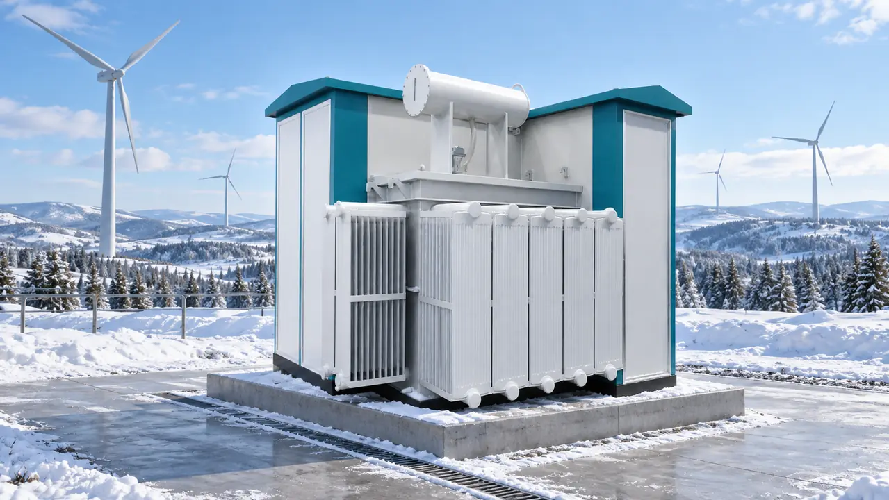
When a commissioning engineer in an illustrative Harbin, China, scenario attempted to energize a ridge-top wind farm after an overnight drop to −32°C, the medium-voltage feeder tripped and oil-pressure indications fluctuated. The apparent transformer fault instead traced to a specification that treated low temperature as one ambient number, not as separate duties affecting liquid flow, seals, control power, heaters and switchgear mechanisms.
Summary: Cold-climate performance should be specified as at least four distinct states: transport and storage, de-energized survival, cold energization, and normal energized operation. Buyers should connect each state to measurable evidence for insulating-liquid viscosity and pour point, sealing materials, heaters, DC/control loads, condensation control, protection inputs and acceptance tests. The IEC 60076 and IEC 62271 series provide relevant transformer and switchgear frameworks, but the project must still define the site temperature envelope, turbine harmonic spectrum and cold-start sequence.
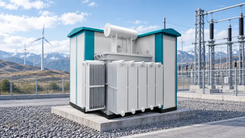
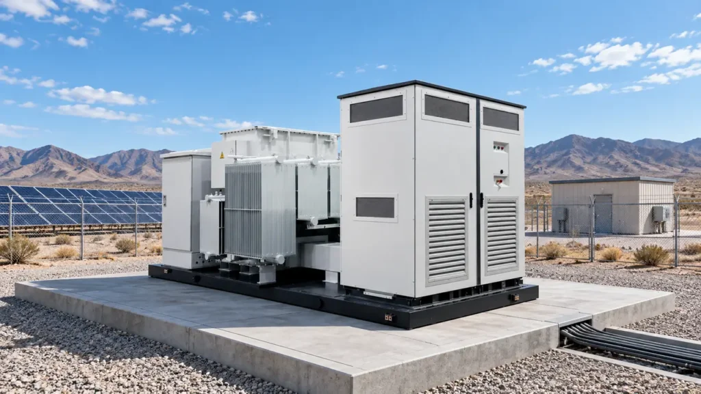
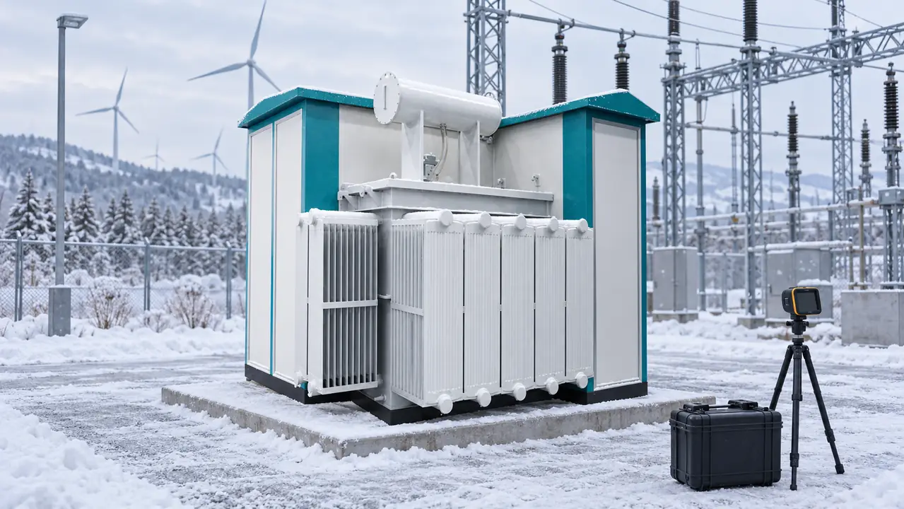
A wind turbine combined transformer places step-up, switching, protection, metering and auxiliary functions in one prefabricated assembly. Integration can reduce field interfaces at remote turbine pads, but a heater, battery, cable seal or motor mechanism can still determine whether the collector node is available.
Which temperature state must the supplier actually guarantee?
“Suitable for −40°C” is incomplete unless the contract says what the equipment must do at that temperature. A unit may tolerate a low temperature while packed and dry, yet require preheating before its first operation. It may survive de-energized cold soak without damage but be unable to operate a switch mechanism, provide stable DC control power or circulate insulating liquid at the same temperature. Normal operation is different again because transformer losses and enclosure heaters create internal heat.
Issue a temperature-state schedule rather than one minimum-ambient value. Include duration, wind exposure, altitude, icing, allowed warm-up time, available auxiliary supply and the required response to loss of station service. Distinguish limits for the complete enclosure from those for individual components.
| State | Required decision | Evidence to request |
|---|---|---|
| Transport and storage | Minimum packed temperature, preservation period and whether heaters or dry storage are required | Packing method, shock/tilt limits, moisture controls, lifting plan and storage instructions |
| De-energized survival | Temperature and duration the assembled unit can withstand without permanent damage | Component temperature ratings, material declarations and post-soak inspection criteria |
| Cold energization | Lowest temperature for applying auxiliary power, operating mechanisms and energizing the transformer | Warm-up sequence, permissives, heater calculation, liquid data and functional test records |
| Normal operation | Load and ambient envelope after stable energized conditions are reached | Loss data, thermal/derating assessment, alarms and loading assumptions |
Require liquid and seal data before accepting a low-temperature claim
Insulating liquid becomes more viscous as temperature falls, which can slow natural convection during cold energization. Require the selected liquid’s viscosity-temperature data and pour point, not merely its fluid family. Pour point is a laboratory characteristic, not a guaranteed energization temperature; the acceptable start also depends on transformer geometry, losses, load pickup and the validated procedure.
Gaskets, cable jackets, bushing seals, conduit and door seals may stiffen or contract at low temperature, changing flange compression and cable-entry sealing. Ask for the material grade or service range, compatible sealant, assembly torque and replacement interval. This evidence distinguishes a cold-weather design from a standard package with a revised ambient label.
Treat condensation and repeated thermal cycling as design loads
Wind generation is variable, so transformer temperature does not follow a steady industrial load. Turbine output, cold nights, solar heating and enclosure heaters cycle windings, bushings, joints and seals. Beyond peak temperature, cycling can promote condensation, loosen marginal connections and repeatedly move sealing interfaces.
Specify anti-condensation heaters, drainage paths, breathers where applicable, cable-entry sealing and enclosure ventilation as one moisture-management system. An IP classification under IEC 60529 describes tested ingress protection; it does not prove that internal humidity will remain safe during every shutdown and restart. Useful monitoring points include compartment temperature, humidity or condensation alarms, heater status and loss-of-auxiliary-supply indication.
Make the electrical design reflect the turbine converter and collector network
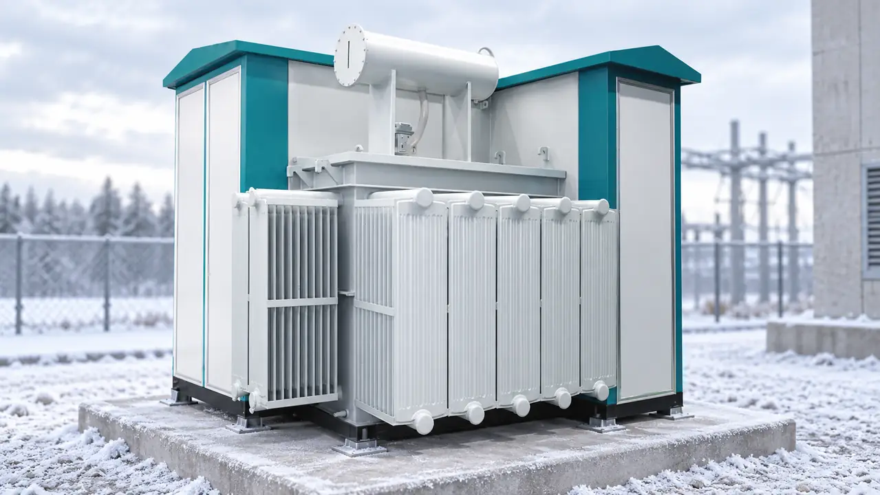
A “35 kV combined transformer” nameplate does not define a complete collector node. The purchase specification should state rated voltage and maximum system voltage, insulation levels, frequency, earthing method, clearances, short-time withstand requirements and expected fault levels. It should also identify transformer impedance and tolerances, cable lengths, switching device, surge-arrester type and location, transformer-terminal arrangement, and who owns the insulation-coordination study.
Switching transients depend on the network around the transformer. Collector cables, switching operations, arrester placement and grounding affect terminal duty. IEC 60076-3 addresses insulation levels and dielectric tests; project-specific insulation coordination must still match the actual cable and protection layout.
Specify the harmonic spectrum instead of relying on one THD value
Converter-fed turbine output can contain harmonic current, and harmonic frequency changes winding eddy and other stray losses. One total harmonic distortion value can hide orders and operating points relevant to loss evaluation. Require the project harmonic-current spectrum, fundamental current, operating range and aggregation assumptions at the transformer terminals, then require the transformer supplier to show how those inputs informed its assessment.
Variable loading also matters. Provide a representative power-versus-time profile, expected curtailment and overload cases rather than assuming continuous nameplate output. IEC 60076-7 offers loading guidance for oil-immersed transformers, but the project model must still use the agreed ambient, loss and loading inputs. Generic THD and ambient labels are not design inputs; traceable project data is.
Close protection ownership from turbine terminals to the collector feeder
Protection engineering needs maximum and minimum fault levels, grounding method, vector group, impedance, converter fault-current behavior, cable data and upstream clearing times. Assign CT/VT ratios, classes and burdens; relay settings; switch duties; alarms; trip logic; interlocks; SCADA points; and ownership of the coordination study.
Where lightning protection is part of the wind-farm design, IEC 61400-24 provides the relevant wind-turbine context. It does not replace the collector-system surge and grounding study. Relay test sheets should show the approved settings baseline, test currents or voltages, trip path and remote indication—not merely that a relay powered up.
Size heaters and control power from the complete cold-start sequence
List every auxiliary load by source, voltage range, steady and starting demand, and required autonomy. Loads may include heaters, thermostats, battery charger, DC supply, relays, communications, motor operators, ventilation and monitoring. Heater calculations should cover enclosure loss, infiltration, target temperature, warm-up time and heat distribution.
Control batteries and chargers deserve the same scrutiny. State the battery chemistry, capacity basis, lowest qualified temperature, heater demand if used, charger recovery time and required trip/close operations after loss of AC supply. If the cold-start sequence depends on external station service, identify where that supply originates and how the unit recovers after a prolonged outage.
For an illustrative compartment calculation, assume 250 kg of steel and equipment with an effective heat capacity of 0.50 kJ/kg·K. Raising it by 20 K stores about 2,500 kJ; over two hours that is an average 0.347 kW before enclosure losses. If calculated losses are 0.45 kW and a 25% engineering margin is applied, the example heater duty is about 1.0 kW. This is not a transformer or enclosure design result—it excludes the oil mass, wind infiltration, local hot spots, control tolerances and manufacturer validation—but it shows why the warm-up time and loss assumptions belong in the calculation.
Define FAT, SAT and winter recovery evidence before award
Factory acceptance testing should tie the approved drawings and settings to serial-numbered equipment. In addition to agreed transformer routine tests, the project FAT can cover wiring continuity, heater and thermostat operation, alarm and trip logic, interlocks, motor mechanisms, DC-load checks, SCADA point simulation and document review. If a cold-soak or environmental test is required, define chamber temperature, stabilization time, energized or de-energized state, permitted preheat, operations to be performed and pass/fail criteria. A cold test method is not automatically a certification of the entire package.
Site acceptance testing should verify what shipment and installation can change: oil or liquid condition where applicable, insulation checks, torque and cable terminations, earthing, CT/VT polarity, relay settings, trip paths, remote indications, heater supplies and the approved energization sequence. Record ambient and internal temperature during a cold start so the result can be compared with the contractual boundary.
| Decision area | Minimum project input | Supplier or contractor evidence |
|---|---|---|
| Electrical and thermal duty | Load profile, harmonic spectrum, ambient states, system voltage and fault levels | Guaranteed losses and impedance, thermal assessment, liquid data and rating schedule |
| Protection and transients | Collector cables, grounding, turbine fault behavior and switching arrangement | CT/VT schedule, relay files, coordination inputs, insulation data and arrester interfaces |
| FAT and SAT | Witness points, acceptance limits and responsible parties | Approved procedures, calibrated records, settings baseline, deviation list and signed results |
| Logistics and civil work | Route, crane limits, foundation tolerances and winter access | Mass and center of gravity, lifting drawing, anchoring loads and installation clearances |
| Winter recovery | Target repair time and site skill level | Critical-spares list, storage conditions, replacement procedures and support contacts |
Winter spares should follow failure consequence and lead time, not a generic percentage of purchase price. Consider heater elements and thermostats, door and cable-entry seals, mechanism lubricants approved for the temperature range, control fuses, relay or power-supply modules, indication devices and the tools needed to replace them safely. Store elastomers, batteries and electronic spares within their declared conditions, and rehearse access when snow, ice or crane restrictions may extend an outage.
Use a procurement gate that compares lifecycle exposure, not labels
- Freeze the four-state temperature envelope and the permitted cold-start sequence.
- Issue turbine converter data, load and harmonic profiles, collector cable data, fault levels and grounding assumptions.
- Obtain transformer impedance/loss data, liquid curves, seal information, auxiliary-load schedules and protection inputs.
- Assign responsibility for relay settings, CT/VT selection, insulation coordination, SCADA, civil interfaces, FAT and SAT.
- Compare route, lifting, foundation, service access, warm-up delay, critical spares and outage recovery as total-cost drivers.
At this decision stage, buyers can use Jubang Group’s wind power combined transformer as a starting point for discussing ratings, compartment interfaces and a documented cold-climate schedule. Accept evidence for each operating state, not one unqualified low-temperature claim.
Use these six questions to close common specification gaps
What is a Wind Power Combined Transformers?
A wind power combined transformer is a packaged arrangement that combines a turbine step-up transformer with selected switching, protection, control and enclosure functions. The exact boundary varies, so review the single-line diagram, compartment layout and responsibility schedule rather than relying on the product name.
What voltage do wind turbines use before grid connection?
Turbine generator or converter output is stepped up to the wind-farm collection voltage, but the exact voltages depend on the turbine and network design. Confirm rated and maximum system voltage, insulation levels and earthing rather than treating “35 kV” as the complete electrical specification.
Why are combined transformers used in wind farms?
They can consolidate factory-defined interfaces and reduce field assembly at repeated turbine pads. Their value depends on documented access, lifting, protection, auxiliary power and maintenance boundaries; integration alone does not guarantee faster commissioning.
How do low temperatures affect wind power transformers?
Cold can increase insulating-liquid viscosity, stiffen seals and cables, reduce battery capability, slow mechanisms and increase condensation risk during thermal cycling. Specify survival, energization and normal operation separately, then verify liquid, material, heater and control-power evidence for each state.
What protection equipment is integrated in a wind farm substation?
Functions may include overcurrent and earth-fault relays, transformer temperature or pressure alarms, surge protection, interlocking, metering and remote indications. The project protection study must define settings and coordination using actual CT/VT, fault and converter data.
How do you select a wind turbine step-up transformer?
Start with turbine power and converter data, voltage ratio, vector group, impedance, loss evaluation, insulation level, harmonic spectrum, fault duty and the four-state environmental envelope. Then compare access, auxiliaries, test evidence and service strategy across a combined transformer configuration and any project-permitted separate arrangement.
Which standards and contract records support the final decision?
IEC 60076-1 frames general power-transformer requirements; IEC 60076-3 addresses insulation levels and dielectric tests; and IEC 60076-7 addresses loading guidance for oil-immersed transformers. IEC 62271-202 is relevant to prefabricated high-voltage/low-voltage substations. The applicable edition, equipment scope, purchaser options and project acceptance criteria should be named in the contract. Compliance with a test method is not the same as independent product certification, and none of these references replaces destination-market requirements.
Use primary standards pages to verify scope and current editions
- IEC search: IEC 60076-1, Power transformers—General
- IEC search: IEC 60076-3, insulation levels and dielectric tests
- IEC search: IEC 60076-7, loading guide for oil-immersed transformers
- IEC search: IEC 62271-202, prefabricated substations
- IEC search: IEC 61400-24, wind turbine lightning protection
The best cold-climate package is not the one with the lowest number on a brochure; it is the one whose transport, survival, start and operating boundaries are proven and usable. When the technical schedule is ready, review the MV switchgear interface and contact Jubang Group to discuss a documented combined-transformer configuration for the project.