From transformers and switchgear to ring main units, substations, circuit breakers and smart components, Jubang provides integrated product support for power distribution projects.
Discover Jubang’s strengths in technology R&D, quality testing and smart manufacturing, supporting reliable electrical equipment and efficient power distribution solutions for global customers.
From technical consultation and OEM/ODM customization to EPC support, smart O&M, delivery documentation and after-sales service, Jubang supports your project at every stage.
Explore Jubang Group’s development history, intelligent manufacturing base, R&D platforms, CNAS-accredited laboratory and global project service capabilities.
Current Transformers vs CT Transformers: What’s the Difference?
Release Time: 2026-08-18
When a distribution technical engineer in Kuala Lumpur encountered inconsistent feeder readings during a Southeast Asian switchgear commissioning project, he had already watched a wiring tutorial, checked the supplier quotation and confidently energized the metering circuit. Within two hours, the meter was outside the expected tolerance; a protection relay then issued a nuisance trip, and the overseas project procurement manager in Dubai faced a delayed handover. The equipment was not defective. The team had treated a protection core and a metering core as interchangeable—and the search phrase “current transformers vs CT transformers” had concealed the real selection problem.
Summary: Current transformers and CT transformers are the same instrument-transformer category; “CT transformer” is simply redundant industry shorthand. The commercial risk lies not in the name but in ratio, burden, accuracy class, core design and saturation performance. IEC 61869-2 covers inductive units for 15–100 Hz systems. Project teams should specify metering and protection duties separately, calculate the connected burden, and coordinate the CT data with switchgear, substations, meters and relays before purchase.
Current transformers convert a high primary current into a standardized, isolated secondary signal that a meter or protective relay can use. Typical secondary ratings are 1 A or 5 A. Unlike a power transformer, a CT transformer provides signal scaling and isolation rather than energy delivery. IEC 61869-2 is the principal product standard for newly manufactured inductive units and, according to the IEC, replaces IEC 60044-1 and IEC 60044-6 while adding requirements for transient performance. That standards history explains why specifications from different projects may use different vocabulary even when they refer to the same equipment family.
Real metal-clad switchgear context: CT selection must be coordinated with the panel, meter and protection relay rather than treated as an isolated component purchase.
Are Current Transformers and CT Transformers the Same Device?
Yes. “CT” is the accepted abbreviation for current transformer, so “CT transformer” literally expands to “current transformer transformer.” Engineers still use the redundant phrase in requests for quotation, search queries and site conversations; it does not identify a separate topology, insulation system or accuracy category.
In other words, catalogs may list current transformers under a CT transformer heading, but the submittal still needs the same electrical, mechanical and test data.
The honest answer is simple in terminology but demanding in engineering. IEC 61869-2 separates measuring and protective behavior: an 800/5 A, class 0.5, 10 VA unit is not equivalent to an 800/5 A, 5P20, 15 VA unit. The first targets metering accuracy; the second describes high-fault-current behavior.
Primary current: selected from the circuit’s normal and emergency loading, such as 800 A.
Secondary current: normally 1 A or 5 A; 1 A materially reduces lead losses over long cable runs.
Rated frequency: IEC 61869-2 covers 15 Hz to 100 Hz, encompassing common 50 Hz and 60 Hz projects.
Duty: measuring, protection, or separate cores for both; a label must make the distinction explicit.
How Does a Current Transformer Produce a Usable Signal?
The primary conductor creates core flux; the secondary winding produces a proportional current. In an ideal 800/5 A design, 800 A corresponds to 5 A, a 160:1 ratio. Real performance also depends on magnetizing current, core material, impedance and waveform. IEC 61869-1 gives general requirements, while IEC 61869-2 adds current-specific requirements.
The secondary must never be opened while primary current flows. For current transformers, removing the ampere-turn balance can create a dangerous voltage across open terminals; excessive flux can also heat or permanently magnetize the core. Commissioning practice therefore uses shorting terminals and a defined grounding point, with all work completed under the project’s electrical safety procedure.
Which four quantities control the actual ratio error?
Ratio: meters and relays must use the nameplate primary/secondary ratio.
Burden: device input, both leads and terminal resistance form the secondary VA load.
Accuracy class: “0.2,” “0.5,” “5P” and “10P” communicate different IEC error limits.
Saturation margin: the core must reproduce fault current long enough for the protection scheme to trip.
Lead burden illustrates the hidden interaction. Because copper loss follows I²R, the same loop resistance produces 25 times more VA burden at 5 A than at 1 A. That is why a remote relay room can turn a seemingly economical 5 A selection into larger cables, higher error or a redesign.
Why Are Metering and Protection Cores Not Interchangeable?
A metering core is designed for accuracy around normal operating current and is usually intended to saturate earlier during a severe fault, limiting current delivered to the instrument. IEC terminology uses an instrument security factor, FS, for this behavior. For example, an FS5 marking indicates a security-related limit at five times rated primary current under specified burden conditions.
When one CT transformer contains both measuring and protection cores, each core must retain its own ratio, class, burden and terminal identification; a shared housing does not create shared performance.
A protection core has the opposite priority: it must remain sufficiently faithful at multiples of rated current. A 5P20 marking expresses a 5% protection composite-error class with an accuracy limit factor of 20 at rated burden. A low-loss relay is no guarantee; leads, terminals, connections and actual short-circuit level still affect the required excitation voltage.
For differential, restricted earth-fault or high-impedance schemes, a generic P class may be insufficient. Knee-point voltage, winding resistance, excitation and transient data may be required—especially where DC offset can drive the core into saturation.
What Hidden Costs Appear When the Core Is Selected Incorrectly?
The purchase price of a CT transformer is usually small beside the installed system value, yet an error can propagate through engineering, factory testing, commissioning and operations. A procurement comparison should therefore use total cost of ownership, not unit price alone.
Engineering rework: ratio changes can reopen drawings, relay settings, labels and test sheets.
Physical rework: window, busbar and clearance conflicts can block a late substitute.
Revenue leakage: the wrong class or burden can bias lifetime energy measurement.
Availability loss: saturation can delay protection; wrong polarity can create false differential current.
Test repetition: replacement can repeat ratio, polarity, insulation and excitation checks.
A practical ROI test compares the added cost of separated cores, test evidence and coordinated wiring with one avoided trip or site replacement. On critical infrastructure, that event commonly dominates the component-price difference.
Selecting the CT transformer against the full secondary circuit is therefore an availability decision as much as a component decision.
Current Transformers vs CT Transformers: Technical and Commercial Comparison
Decision dimension
“Current transformer”
“CT transformer”
Procurement implication
Technical meaning
Formal generic equipment name
Redundant shorthand for the same equipment
No price or performance difference follows from wording alone
Typical output
1 A or 5 A secondary
1 A or 5 A secondary
Match meter, relay and cable design
Measuring duty
Examples: class 0.2, 0.5; FS may be stated
Same IEC designations
Check burden and billing requirements
Protection duty
Examples: 5P20 or 10P classes
Same IEC designations
Verify fault current, ALF and relay scheme
Compatibility
Depends on ratio, burden, dimensions, insulation and terminals
Depends on exactly the same data
Do not approve a substitute by name alone
TCO risk
Low when the complete secondary circuit is coordinated
Identical when specifications are identical
Evaluate system evidence, not terminology
Selection Matrix by Application and Performance Level
Application
Typical selection direction
Key verification
Cost driver
Utility or revenue metering
Dedicated measuring core; project-defined class such as 0.2 or 0.5
Accuracy across the specified current range, actual VA burden, sealing and local metering rules
Higher-accuracy core and certification evidence
MV feeder overcurrent protection
P-class core such as 5P20, subject to study
Maximum fault current, ALF, relay burden and lead resistance
Core cross-section and short-circuit duty
Transformer differential protection
Matched characteristics or transient-class data as required
Ratio compensation, polarity, knee point, winding resistance and through-fault stability
Engineering study and matched test data
Prefabricated substation metering plus protection
Two separate cores or separate devices
Switchgear space, thermal current, cable route and terminal allocation
Multi-core construction and compact integration
Long secondary cable run
Consider 1 A secondary
Calculated loop resistance and relay input rating
Copper cable size versus compatible relay/meter input
This matrix is a starting point, not a substitute for the protection coordination study. In Southeast Asia and the Middle East, 50 Hz systems are common, but utility practices, ambient temperature, altitude, metering approval and short-circuit levels vary by country and project. The specification must reconcile every local requirement with the IEC baseline.
Which Standards and Certifications Matter?
IEC 61869-1 establishes general requirements for instrument transformers; IEC 61869-2 adds the requirements specific to inductive current transformers. Current transformers installed inside AC metal-enclosed switchgear above 1 kV and up to and including 52 kV also sit within the assembly-level design and testing context of IEC 62271-200. A power transformer application may additionally bring IEC 60076 into the equipment package, although it does not replace the instrument-transformer requirements.
CE, CB and KEMA-KEUR documents can support market access or third-party confidence for applicable products; ISO 9001 addresses the quality system, not a core’s accuracy. Buyers should verify certificate scope, issuer, standard edition and model—a brochure logo is not traceable evidence.
Nonconformity can produce more than a technical deviation. It may trigger consultant rejection, failed factory acceptance testing, customs or market-access delays, warranty disputes and loss of utility approval. The commercial safeguard is a document schedule that links each datasheet value to the approved drawing, applicable standard and test record.
How Should a Buyer Specify the Right CT?
We recommend treating every CT transformer as one interface in a complete protection-and-measurement chain, not as a catalog ratio selected in isolation.
Separate every duty. State which core serves billing, indication, overcurrent, earth fault or differential protection; assign a unique terminal designation and polarity mark.
Calculate rather than guess the burden. Add device inputs, two-way lead resistance and terminal allowances, then retain a documented margin without oversizing so far that instrument protection is compromised.
Coordinate normal and fault current. Select a ratio that preserves useful measurement resolution while avoiding continuous overload; verify short-time thermal and dynamic current against the system study.
Freeze mechanical interfaces early. Confirm window or bar dimensions, mounting, insulation level, creepage, terminal accessibility and the available compartment envelope.
Demand traceable evidence. Review nameplate data, routine-test results, relevant type-test reports, excitation data when required, and certificate scope before shipment.
Jubang Group provides coordinated switchgear and ring main units, prefabricated substations, power transformers and complete power-distribution solutions with a CNAS-accredited laboratory capability and an ISO 9001 quality framework. Its qualification profile also includes national high-tech enterprise status, 165 invention patents, 45 software copyrights, and approved-supplier credentials for State Grid Corporation of China and China Southern Power Grid. For a buyer, the relevant value is not a standalone badge; it is the ability to coordinate the instrument-transformer data with the complete panel, transformer, EPC interface and commissioning evidence.
Frequently Asked Questions
Is a CT transformer the same as a current transformer?
Yes. CT already means current transformer, so the longer phrase is redundant shorthand. The CT transformer label does not determine performance; the ratio, class, burden, frequency, insulation level and saturation data do.
What is the difference between a CT and a power transformer?
A CT scales primary current into a low standardized signal for measurement or protection, typically 1 A or 5 A. A power transformer transfers electrical power between voltage levels. A project team comparing both can review the 6–10 kV oil-immersed power transformer context, where measurement and protection CTs form only part of the wider system.
Can a protection CT be used for metering?
Not by assumption. A protection core is optimized to avoid premature saturation during faults, while a metering core prioritizes accuracy at normal current and may limit instrument current during severe faults. The required measuring class and FS must be explicitly verified.
Why is a CT secondary rated 1 A or 5 A?
Both ratings standardize the interface to meters and relays. A 1 A circuit reduces I²R lead burden to one twenty-fifth of the 5 A burden for the same resistance, which can be advantageous over long distances; connected devices must support the chosen rating.
How is a CT selected for switchgear?
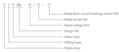
The engineer checks load current, maximum fault current, ratio, secondary rating, accuracy class, burden, ALF or FS, short-time withstand, insulation, dimensions and relay inputs. Current transformers should then be coordinated with the KYN28A-12 metal-clad switchgear layout, while the CT transformer approval remains tied to the project protection study.
The difference is not in the two names—it is in the measurement, protection and commercial decisions that follow. Jubang Group builds coordinated switchgear, substations, transformers, EPC delivery and intelligent O&M solutions for that moment. Explore Jubang Group’s power-distribution capabilities and contact the technical team with the single-line diagram, load schedule, fault level and relay requirements for a project-specific review.
Products are exported to more than 100 countries and regions such as Africa, the Middle East, and the United Kingdom and Europe. It is a leading manufacturer of power distribution equipment in China.

 JUBANG