From transformers and switchgear to ring main units, substations, circuit breakers and smart components, Jubang provides integrated product support for power distribution projects.
Discover Jubang’s strengths in technology R&D, quality testing and smart manufacturing, supporting reliable electrical equipment and efficient power distribution solutions for global customers.
From technical consultation and OEM/ODM customization to EPC support, smart O&M, delivery documentation and after-sales service, Jubang supports your project at every stage.
Explore Jubang Group’s development history, intelligent manufacturing base, R&D platforms, CNAS-accredited laboratory and global project service capabilities.
Impedance Explained: Resistance, Reactance and AC Circuit Examples
Release Time: 2026-11-11
Impedance describes the relationship between AC voltage and current, including both magnitude and phase. For a linear circuit at one sinusoidal frequency, it can be written as Z = R + jX, where R is resistance, X is net reactance and j identifies the quadrature component. Impedance and its components are expressed in ohms.
Its magnitude is |Z| = √(R² + X²). That is why adding resistance and reactance as ordinary positive numbers does not generally give the impedance magnitude.
Resistance and reactance describe different effects
Resistance is the in-phase component of this AC relationship. Reactance accounts for the quadrature component associated with ideal inductive or capacitive behaviour. For a series RLC equivalent, the net reactance is X = XL − XC.
Positive net X is inductive in this convention; negative net X is capacitive. The sign carries information about phase, even though both cases can have the same impedance magnitude. Removing the sign too early can leave the current calculation’s magnitude correct while losing the lead/lag interpretation.
Keep the full value Z distinct from |Z|. Writing “5 Ω” as a magnitude answers how large the impedance is. Writing a complex value or a magnitude with its phase also states the relative phase information. The two descriptions should not be silently treated as equivalent.
Why frequency belongs with an impedance value
For ideal components, XL = 2πfL and XC = 1 / (2πfC), with f in hertz, L in henries and C in farads. The resulting reactances are in ohms. Increasing frequency increases an ideal inductor’s reactance and decreases an ideal capacitor’s reactance.
This makes an unexplained impedance value incomplete for a reactive network. A value established at one frequency should not automatically be used at another. The circuit topology and component models must also match the calculation.
The series expression above is a useful starting point because the same current passes through the series elements. It is not permission to add the magnitudes of arbitrary parallel branches. First establish the equivalent circuit, then use the relationship that applies to it.
Worked example: 3 + j4 Ω at 50 Hz
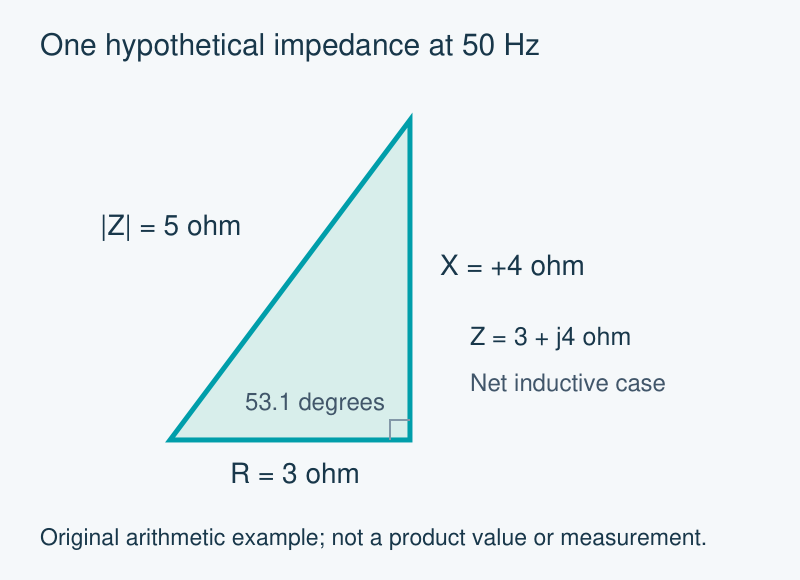
Assume a hypothetical linear series equivalent at 50 Hz with resistance R = 3 Ω and net inductive reactance X = +4 Ω. The reactance is an assumed net value at that frequency. These are chosen teaching inputs, not component test results or transformer specifications.
The complex impedance is Z = 3 + j4 Ω. Its magnitude is √(3² + 4²) = √25 = 5 Ω. It is not 3 + 4 = 7 Ω, because the resistive and reactive components are perpendicular in this representation.
The horizontal and vertical legs represent the assumed 3 Ω resistance and +4 Ω reactance. The 5 Ω hypotenuse is the impedance magnitude. The angle is approximately 53.1°; this is an original arithmetic example.
Now apply an assumed sinusoidal 100 V RMS across that equivalent. The current magnitude is 100 / 5 = 20 A RMS. The phase angle is arctan(4 / 3) = 53.1°, approximately. Because the net reactance is inductive, current lags the applied voltage in this example.
A second check reconstructs the assumed voltage components: 20 × 3 = 60 V across the resistive component and 20 × 4 = 80 V across the net reactive component. Their vector magnitude is √(60² + 80²) = 100 V, matching the input. Simply adding 60 V and 80 V would make the same scalar-addition mistake.
What the example does and does not establish
The example demonstrates a steady sinusoidal relationship at the stated frequency. It does not predict a switching transient, core saturation or the response to an arbitrary distorted waveform. The simple equivalent and its assumptions define what the answer means.
RMS quantities also need to remain consistent. The 100 V input and 20 A result use the same RMS basis. Substituting a peak voltage while continuing to label the result RMS would change the calculation without acknowledging it.
A reproducible note therefore records the equivalent circuit, frequency, resistance, net reactance and voltage/current basis. Those details let another reader distinguish an arithmetic error from a change in the model or operating conditions.
Impedance in ohms is not a transformer percentage
Equipment documents may express related impedance information on a different basis. For example, the published JUBANG 35 kV oil-immersed transformer catalogue includes a short-circuit impedance field expressed as a percentage. That percentage should not be inserted directly as an ohm value in the example above.
Check the unit and reference basis before using equipment data. Converting or applying a transformer percentage belongs to a separate equipment calculation with the appropriate rating information; the general 3–4–5 Ω example does not perform that task.
Products are exported to more than 100 countries and regions such as Africa, the Middle East, and the United Kingdom and Europe. It is a leading manufacturer of power distribution equipment in China.

 JUBANG