From transformers and switchgear to ring main units, substations, circuit breakers and smart components, Jubang provides integrated product support for power distribution projects.
Discover Jubang’s strengths in technology R&D, quality testing and smart manufacturing, supporting reliable electrical equipment and efficient power distribution solutions for global customers.
From technical consultation and OEM/ODM customization to EPC support, smart O&M, delivery documentation and after-sales service, Jubang supports your project at every stage.
Explore Jubang Group’s development history, intelligent manufacturing base, R&D platforms, CNAS-accredited laboratory and global project service capabilities.
Transformer Sizing Chart: kVA, Full-Load Current and Load Inputs
Release Time: 2026-11-09
A transformer sizing chart can convert a stated kVA rating and voltage into theoretical full-load current. It cannot determine the final transformer size without the expected load, phase arrangement and operating conditions. Use the chart below for preliminary balanced three-phase planning, then verify the demand and the offered equipment.
These values use IL = 1000 × kVA / (√3 × VLL), with RMS line-to-line voltage and RMS line current. Each result is rounded to one decimal place. The listed capacities are illustrative calculation points, not a JUBANG stock list or a promise that every voltage/rating combination is available.
Illustrative capacity
At 400 V line-to-line
At 480 V line-to-line
100 kVA
144.3 A
120.3 A
250 kVA
360.8 A
300.7 A
500 kVA
721.7 A
601.4 A
1000 kVA
1443.4 A
1202.8 A
1600 kVA
2309.4 A
1924.5 A
For example, the 500 kVA/400 V entry is 500,000 / (√3 × 400) = 721.687… A. The current is higher at 400 V than at 480 V for the same kVA because the voltage denominator is smaller.
Use the voltage on the side being evaluated. A secondary-current entry is not the primary current, and a balanced three-phase table is not a single-phase table. These results also do not select a conductor, fuse or circuit-breaker rating.
Start with demand, not the next attractive chart row
The initial load information should distinguish connected equipment from the load expected to operate together. A nameplate total may not describe the project’s operating demand. The design team must establish the appropriate demand basis, operating states and applicable requirements before a capacity is chosen.
If the known demand is expressed in kW, the corresponding power factor is needed to calculate kVA. As an original example, assume a demand of 350 kW at PF 0.90. The apparent power is 350 / 0.90 = 388.9 kVA, approximately, before any separately justified project allowances.
That calculation does not mean that 388.9 kVA is an available product or that the next row in this chart is automatically suitable. The selected capacity must be checked against the load and service conditions. If the load is already stated in kVA, dividing it by power factor again would double-count the conversion.
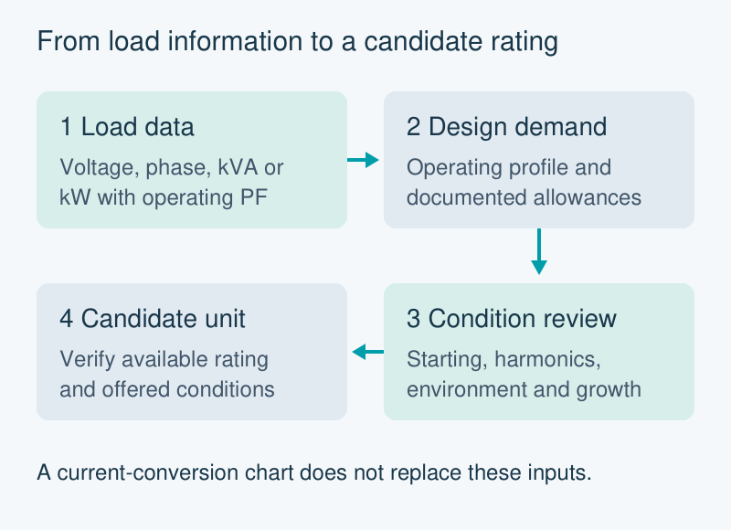
Preliminary selection workflow. The current-conversion chart supports the calculation; it does not replace the demand, operating-condition or offered-rating reviews.
Which load inputs can change the selection?
Operating profile. Identify which loads run together, their duty cycles and the operating states that matter. A single average value can conceal the case that actually governs the enquiry. Keep the load schedule and its assumptions together.
Motor starting. Steady running kVA does not describe the starting event. Supply the motor information, starting method, starting frequency and acceptable voltage behaviour for the engineering review. Do not apply one generic starting multiplier to every motor and transformer combination.
Non-linear loads. Identify drives, electronic loads and other harmonic-producing equipment. Their current characteristics may need a separate thermal and neutral assessment. A balanced fundamental-frequency calculation alone does not establish suitability for every load waveform.
Site conditions. Ambient conditions, altitude, ventilation and installation arrangement should accompany the load information. The supplier needs to assess the proposed equipment against the actual service conditions, rather than a chart’s unstated environment.
Make capacity allowances traceable
Future expansion is a project decision, not a universal percentage. Record the expected additional loads and when they are likely to enter service. If the demand calculation already includes growth or spare capacity, identify that allowance before adding another one.
A practical enquiry distinguishes three values: the present design demand, each justified adjustment, and the resulting capacity requirement. This lets the supplier explain why an available rating is proposed. An unexplained jump from connected kW to a catalogue size is harder to assess, even when the chosen unit looks generously sized.
The phrase “standard transformer sizes” also needs a product context. Available ratings depend on the manufacturer, voltage combination, phase and construction. Confirm those combinations in the current offered range instead of treating a generic chart as a universal catalogue.
What to send with a transformer enquiry
Send the load schedule, primary and secondary voltages, phase/connection requirements, operating profile and site conditions. Identify starting or harmonic information that is available and the questions still awaiting engineering review. Ask for the proposed rating and the conditions on which that proposal depends.
JUBANG’s published oil-immersed distribution-transformer family is a starting point for that equipment discussion. The theoretical chart above neither establishes a model’s availability nor replaces the supplier’s configuration-specific data.
Products are exported to more than 100 countries and regions such as Africa, the Middle East, and the United Kingdom and Europe. It is a leading manufacturer of power distribution equipment in China.

 JUBANG