From transformers and switchgear to ring main units, substations, circuit breakers and smart components, Jubang provides integrated product support for power distribution projects.
Discover Jubang’s strengths in technology R&D, quality testing and smart manufacturing, supporting reliable electrical equipment and efficient power distribution solutions for global customers.
From technical consultation and OEM/ODM customization to EPC support, smart O&M, delivery documentation and after-sales service, Jubang supports your project at every stage.
Explore Jubang Group’s development history, intelligent manufacturing base, R&D platforms, CNAS-accredited laboratory and global project service capabilities.
RMU Load Break Switch vs Circuit Breaker: Protection Responsibilities
Release Time: 2026-07-30
RMU load break switch vs circuit breaker is a question about responsibility, not superiority. A load break switch makes and breaks load currents and provides isolation, but it is not designed to interrupt short-circuit currents. A circuit breaker can make, carry, and break fault currents under protection control. In a ring main unit, those two capabilities are assigned to different ways for different jobs.
The practical consequence for buyers: before requesting a quotation, define which way of the unit sectionalises the ring, which way protects the transformer tee-off, and where fault-clearing responsibility actually sits — in the unit, or upstream at the source substation.
Part 1. What separates an RMU load break switch from a circuit breaker?
Start from what each device is certified to do. IEC 62271-103 covers switches and switch-disconnectors for their switching function, with making and breaking current ratings — the load break switch category. IEC 62271-100 covers alternating-current circuit-breakers, the devices built to interrupt fault current. The distinction sounds academic until a fault occurs and only one of the two can clear it.
Selection question
Load break switch way
Circuit breaker way
What does it switch?
Load currents, ring sectionalising, isolation
Load currents plus fault currents
What happens during a downstream fault?
Carries the fault for its rated short time; something else must clear it
Protection philosophy, relay and sensor interfaces, tripping duty
What should not be assumed?
That it can interrupt a short circuit
That a breaker way is justified on every feeder
Both devices normally sit inside the same sealed assembly, which as a whole falls under the metal-enclosed switchgear scope of IEC 62271-200. The ring main unit is therefore best read as a small package of assigned duties rather than a single device.
Part 2. How does a ring network split protection responsibilities?
A typical ring main unit serves one secondary substation: two ring ways connect the loop, and one or more tee-off ways feed local transformers. The technical overview of ring main units in secondary substations shows the standard arrangement — switch disconnectors on the incoming ring feeders, and a fused way or breaker way on the transformer feeder.
Responsibility then divides cleanly:
Network element
Normal duty
Who clears a fault there?
Ring cable sections
Load break switch ways sectionalise and reconfigure
Source substation protection, or breaker ways where the scheme includes them
Transformer tee-off
Fuse-switch or breaker way feeds the transformer
The switch-fuse combination or the breaker way at the tee-off
Busbar and unit internals
The assembly carries through-current
Upstream protection, within the assembly’s rated withstand
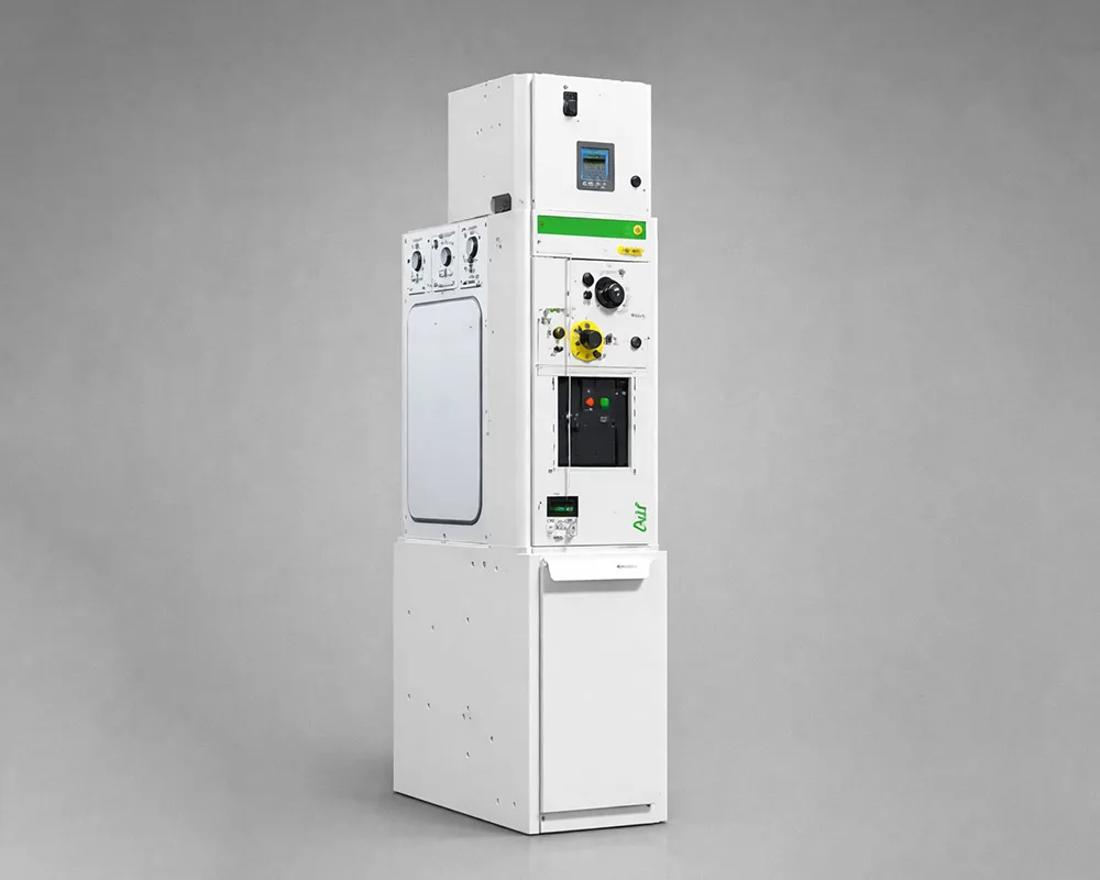
The load break switch’s contribution during a cable fault is operational rather than interruptive: crews open ring switches to isolate the faulted section and restore supply from the healthy side. A configuration overview of a compact gas-insulated family is given in the GT-SRM-12 ring main unit overview; the way mix — how many switch ways, fuse ways, breaker ways — is exactly what a buyer must state per unit.
Part 3. Where does a switch-fuse combination carry the duty?
For distribution transformer tee-offs, ring networks widely use a switch plus current-limiting fuses as one functional device. IEC 62271-105 defines these switch-fuse combinations as assemblies capable of breaking, at rated voltage, any current up to and including their rated short-circuit breaking current — the fuse handles the high-current region, and the switch handles the rest.
Ring-network operating practice reflects that split. The practical guide to ring main unit operation describes the switch fuse as a load-break, fault-make switch equipped with HRC fuses to break fault current, combined with an automatic three-phase trip so that a single fuse operation opens all three phases of the transformer feeder rather than leaving it single-phased.
Buyers should weigh three properties when the fuse way is a candidate:
Clearing behaviour: practitioners note that current-limiting fuses can clear major faults extremely fast — a property valued at transformer tee-offs; the coordination study confirms whether it applies to a given network.
Coverage limits: a fuse is a short-circuit device; sensitive overload protection and electrically initiated tripping usually come from the transformer’s secondary-side protection or from a relay-based way.
Operating consequences: a fuse operation requires a site visit and replacement, so document spare-fuse policy and access in the RFQ.
Part 4. When does a circuit breaker way earn its place?
A breaker way brings relay-controlled interruption into the ring main unit itself. It suits feeders where protection must be selective, adjustable, resettable, or remotely operable — conditions a fuse cannot satisfy alone.
Signals that justify a breaker way
The feeder supplies a critical or high-value load where fast restoration and remote reset matter.
The protection philosophy requires adjustable settings, defined selectivity with upstream and downstream devices, or specific protection functions beyond overcurrent.
The way must integrate with monitoring or a SCADA-connected control centre — trip signalling, status, and remote operation.
The network operator’s scheme assigns fault clearing at this point instead of at the source substation.
Two boundaries keep the decision honest. First, a breaker way needs its measurement and control chain — current sensors or transformers, a relay, auxiliary supply, and tested tripping — which the RFQ must scope explicitly. Second, reclosing practice differs on cable networks: faults on underground cable are mostly permanent, so automatic reclosing is applied cautiously on mainly-cable circuits, a point the ring-operation guide makes directly. Where the duty grows into a full relay-protected feeder line-up rather than a compact ring node, the comparison shifts to withdrawable switchgear — context covered in the outdoor vacuum circuit breaker applications guide.
Part 5. Which ratings assign responsibility between devices?
Rating labels decide whether a device may keep its assigned duty, and the two most confused labels are breaking current and short-time withstand current.
Rating
What it tells you
Which device carries it
Rated breaking current
The current the device can interrupt
Circuit breakers; switch-fuse combinations up to their rated short-circuit breaking current
Rated making capacity
The current the device can close onto safely
Load break switches (fault-make), breakers
Rated short-time withstand current
The current the device can carry, without clearing it, for a rated time
Load break switches, disconnectors, the assembly as a whole
The withstand figure is the one that creates false confidence. A practitioner discussion of two candidate load break switches puts it plainly: to honor a switch’s short-time withstand capability, the upstream protection must isolate the fault within the rated time. A withstand rating is a promise to survive, not a promise to clear — and it holds only when a coordination study proves that some breaking device operates inside the withstand window.
Important: When reviewing an RMU offer, read every way’s ratings against its assigned duty: switching duty and withstand for ring ways, breaking duty for fuse and breaker ways. A rating that does not match the duty is a specification gap, not a bonus. Source context: Eng-Tips discussion of load break switch ratings.
Part 6. Which standards frame each device in an RFQ?
Standards references keep the RFQ language precise without turning the article into a compliance claim. Name the framework, then ask the supplier for the offered design’s documentation against it:
Switches and switch-disconnectors — the load break switch ways: IEC 62271-103.
Alternating-current circuit-breakers — the breaker ways: IEC 62271-100.
Switch-fuse combinations — the transformer tee-off protection: IEC 62271-105.
The metal-enclosed assembly that hosts them: IEC 62271-200.
Naming a standard in an RFQ does not make any offered product compliant, and this article makes no compliance statement for any equipment. The request should ask for type-test documentation, declared ratings per way, and any deviations — reviewed by the project’s responsible engineer.
Part 7. RMU protection RFQ input checklist
A protection-aware RFQ states duties and data; it does not pre-select devices way by way unless the network study already fixed them.
RFQ input list
System voltage, highest voltage for equipment, and neutral earthing practice.
Project fault-level and load data per feeder, supplied from the network study as the basis for ratings — values this article deliberately does not invent.
Way configuration per unit: number of ring ways, transformer tee-offs, and any spare or future ways.
Duty per way: sectionalising, transformer protection, feeder protection — with the expected device category (load break switch, switch-fuse combination, circuit breaker) marked as proposed or open.
Protection philosophy per protected way: fuse expectations, relay functionality, sensor or current transformer needs, auxiliary supply, tripping and alarm interfaces.
Upstream protection context and who owns coordination between the unit and the source substation.
Earthing switches, interlocking sequence, and any cable-test access expectations.
Remote operation and monitoring scope, from none to full control-centre integration.
Standards framework per device family and the required documentation set: declared ratings per way, type-test evidence, drawings, and operating instructions.
Commercial data: delivery, spare fuses or components policy, and the technical contact for coordination questions.
Part 8. Which JUBANG configuration fits which duty?
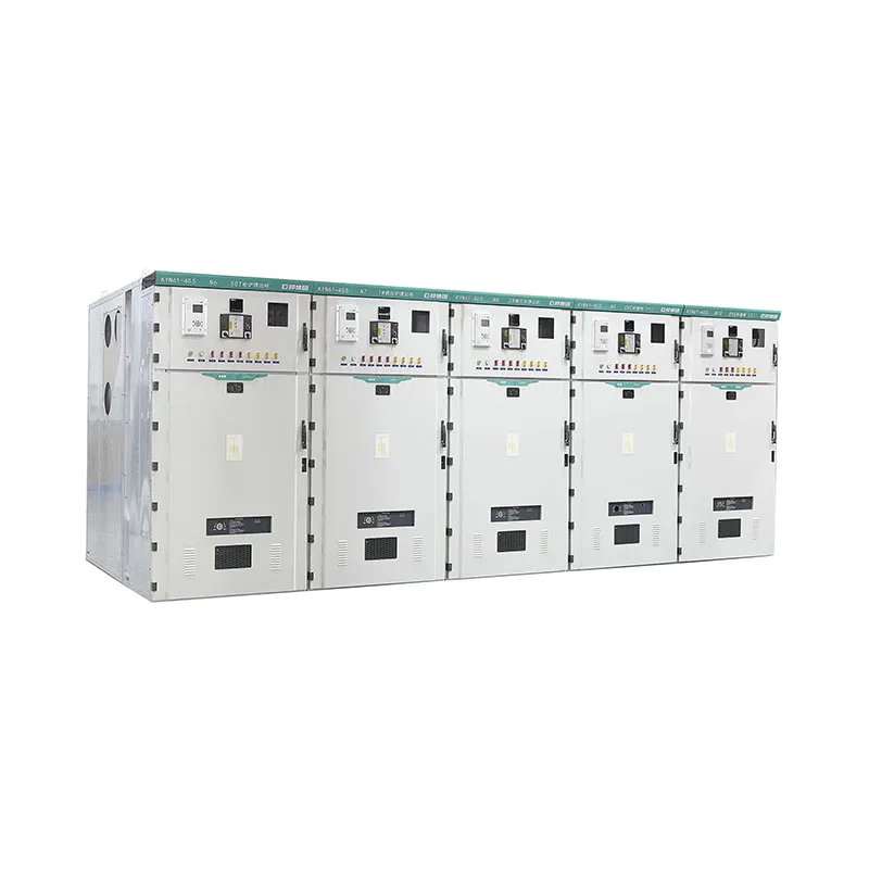
Map the duty split onto product families rather than forcing one product to do everything. For compact ring sectionalising and transformer tee-off duties, the GT-SRM-12 SF6 gas insulated ring main unit page is the starting point for a way-configuration discussion. Where the requirement is a relay-protected, withdrawable feeder line-up — multiple breaker panels, richer protection and measurement — the KYN28A-12 metal clad switchgear page addresses that duty. Solid-insulated and pure-air ring main unit families are deliberately not weighed here: insulation technology is a separate decision axis from protection responsibility, and mixing the two blurs both.
Fit Boundary
A good fit: buyers who can state the duty per way, hold network fault and load data, and need the offered configuration confirmed against those duties.
Not the right path: projects without a fault study or a responsible protection engineer, and single-feeder installations where one breaker panel answers the whole question without a ring unit.
Confirm first: the offered way configuration, declared ratings per way, fuse or relay provisions, coordination responsibility, and the documentation list — in writing from the offered design.
This article assigns no rating, fuse size, relay scheme, or compliance status to any JUBANG product; the offered design’s documentation and the project’s protection study govern those decisions.
Next step:share the way configuration and protection data — network data, duty per way, protection philosophy, and documentation expectations — and request the offered configuration for your ring main unit or switchgear project.
FAQ
What is the difference between a load break switch and a circuit breaker in an RMU?
A load break switch switches load currents and provides isolation; a circuit breaker also interrupts fault currents under relay control. In a ring main unit they occupy different ways: switch ways sectionalise the ring, breaker or fuse ways protect feeders.
Can a load break switch clear a short-circuit fault?
No. It can close onto a fault (fault-make) and carry fault current for its rated short time, but interruption must come from a fuse, a breaker way, or upstream protection. That dependency is why coordination data belongs in the RFQ.
How does a switch-fuse combination protect a distribution transformer?
The current-limiting fuses interrupt high fault currents, and the switch — tripped automatically on any fuse operation — opens all three phases. As a combination it is designed to break any current up to its rated short-circuit breaking current.
When should an RMU use a circuit breaker way instead of a fuse way?
When the feeder needs adjustable, selective, resettable protection, specific protection functions, or remote operation — typically critical loads and network points where the operator assigns fault clearing to the unit itself.
What is the difference between breaking current and short-time withstand current?
Breaking current is what a device can interrupt. Short-time withstand is what it can carry for a rated time while something else clears the fault. A withstand rating without proven upstream clearing inside that time window protects nothing.
Do RMU circuit breaker ways need protection relays?
A breaker way operates through a protection chain: current sensors or transformers, a relay, an auxiliary supply, and a tested trip path. The RFQ should scope that chain explicitly, including settings responsibility and signal interfaces.
Why is automatic reclosing applied cautiously on cable networks?
Because faults on underground cable are mostly permanent, reclosing onto them re-applies the fault rather than restoring supply. Reclosing practice on mainly-cable circuits is therefore conservative and must follow the network operator’s scheme.
Which protection data belong in an RMU RFQ?
Duty per way, network fault and load data, protection philosophy per protected way, upstream coordination context, earthing and interlocking expectations, remote-operation scope, and the documentation set with declared ratings per way.
Products are exported to more than 100 countries and regions such as Africa, the Middle East, and the United Kingdom and Europe. It is a leading manufacturer of power distribution equipment in China.

 JUBANG