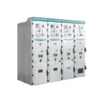
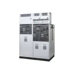
KYN28A-12 Metal Clad Switchgear
KYN28A-12 Metal clad switchgear (hereinafter referred to as switchgear) is suitable for...
From transformers and switchgear to ring main units, substations, circuit breakers and smart components, Jubang provides integrated product support for power distribution projects.
Discover Jubang’s strengths in technology R&D, quality testing and smart manufacturing, supporting reliable electrical equipment and efficient power distribution solutions for global customers.
From technical consultation and OEM/ODM customization to EPC support, smart O&M, delivery documentation and after-sales service, Jubang supports your project at every stage.
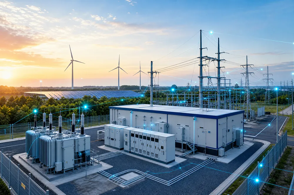
Explore Jubang Group’s development history, intelligent manufacturing base, R&D platforms, CNAS-accredited laboratory and global project service capabilities.


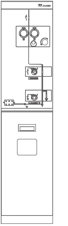
GT-SRM-12 SF6 gas insulated ring main unit (hereinafter referred to as inflatable cabinet) is the latest generation of inflatable cabinet carefully developed by the company in combination with the existing advanced production equipment and manufacturing technology.
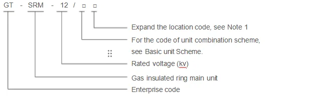
Note 1:Extended position code Meaning: L is left out, R is right out, LR is left and right out, LT is left top out, RT is right top out, blank is no expansion. Illustration:GT-SRM -12 /VCCC-L represents a 12kV four-unit common box cabinet consisting of a circuit breaker unit and three load switch units extended out on the left side.
High strength, high sealing
Safe fully insulated and fully sealed design
GT-SRM-12 SF6 Gas insulated ring main unit is a sealed stainless steel box with the main components of the primary circuit filled with low-voltage SF6 gas as insulation medium. The Incoming and outgoing terminals can be connected by cable plugs, so as to ensure that the ring main unit is fully insulated and sealed, and is not affected by the external environment. The protection level of the gas box reaches IP67. The external parts of the gas box are specially designed and surface-treated, with the functions of anti-condensation and short-term flood resistance.
Standard modular design
Typical unit modules include load switch unit C, load switch and fuse combination electrical unit F, circuit breaker unit V, busbar PT unit P, cable feeder unit B and metering unit M, etc. Different unit modules can be arbitrarily combined to form a common box type inflatable cabinet.
Flexible extended design
GT-SRM-12 SF6 Gas insulated ring main unit can be composed of various standard modules into a common box type non-expandable ring main unit, or different modules can be combined into an expandable unit. Through special busbar connectors, diversified unit feeding can be realized, which can meet the complex and diverse power supply and distribution design schemes of various places in China to the maximum extent.
Special branch box application scheme
According to the domestic market demand, the bus bar of GT-SMR-12 inflatable cabinet can be equipped with left and right outgoing bushing, especially suitable for all kinds of cable distribution boxes with one or more load switches, so as to achieve flexible and economical power distribution scheme.
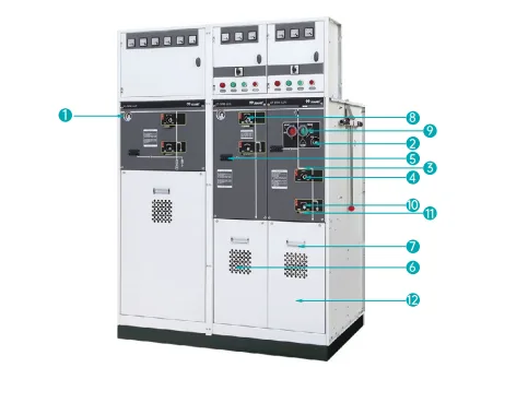
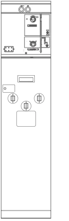
1 Gas-pressure meter
At room temperature, a red pointer indicates low pressure and a green pointer indicates normal pressure.
2 Circuit breaker operating hole
Insert the handle into the operating hole to store energy on the circuit breaker.
3 Operating mechanism room
Operating mechanism adopts spring energy storage design, compact structure, small operating force, long life, optional electric operating mechanism accessories.
4 Isolation switch operating hole
Insert the handle into the operating hole to open and close the isolation switch.
5 Live display
Shows if the high voltage is charged and the jack below the indicator light can be used for secondary nuclear phase.
6 Inspection window
Using explosion-proof glass, through the inspection window can be used to measure the cable head infrared temperature
7 Door handle
Easy to lift the door up and open the front lower door.
8 Load switch operating hole
Plug the handle into the operating hole to open and close the load switch.
9 Open and close button
After the breaker mechanism has stored energy, it can be operated by the button of opening and closing.
10 Earthing switch operating hole
Insert the handle into the operating hole to open and close the earthing switch.
11 Padlock device
Padlock can be configured to prevent unauthorized personnel from misoperation.
12 Cable room
A standard sleeve is provided to connect the Incoming and outgoing cables through a fully insulated fully sealed detachable cable
Load switch Unit C
• The three-station load switch of this unit has three working states of switch on – switch off – earthing, which is mainly used in the connection, branch and control of the Incoming and outgoing lines of the ring network cable line.
Standard configuration and features
• 630A bus bar
• Three-station load
• Three-station single-spring operating mechanism with two independent load switches and earthing switch operating shaft
• Position indication of load switch and earthing switch
• Outgoing bushing located in front horizontal arrangement, 630A 400 series bolt bushing
• Capacitive voltage indicator indicating live casing
• For all switching functions, there is a convenient mounting padlock device on the panel
• SF6 gas pressure gauge (Only one in each SF6 tank)
• Earthing bus
• Cabinet body
Optional configurations and features
• Reserve expansion sleeve
• Expansion busbar
• Electrically operated mechanism
• Short circuit and earth fault indicator
• Ring current transformer and ammeter
• Arrester
• Detachable connector (Cable head)
• Key mechanical interlocking device
• Incoming line live earth latching (latching earthing switch when casing is live)
• Auxiliary contacts
Load switch position 2NO+2NC
Earthing switch position 2NO+2NC
Pressure gauge with signal 1NO
• Secondary device can be installed in secondary instrument box on top of switchgear
Note: According to user requirements, the earthing switch can be canceled and the two-station load switch can be selected.
Load Switch-fuse Combo Appliance Unit F
• The main purpose of this unit is to control and protect distribution transformers of 1250kVA capacity and below.
Standard configuration and features
• 630A bus bar
• Three-station load, the earthing switch at the head of the fuse and the end of the fuse are mechanically linked
• Three-station double spring operating mechanism, there are two independent load switch and earthing switch operating shaft
• Position indication of load switch and earthing switch
• Fuse barrel
• The fuse is placed horizontally
• Fuse trip indication
• Outgoing bushing located horizontally in front, 630A 400 series bolt bushing
• Capacitive voltage indicator indicating live casing
• For all switching functions, there is a convenient mounting padlock device on the panel
• SF6 Gas pressure gauge (Only one in each SF6 tank)
• Earthing busbar
• Fuses for transformer protection
• Cabinet body
Optional configurations and features
• Reserve expansion sleeve
• Expansion busbar
• Electrically operated mechanism
• Parallel trip coil 24V/48V DC,110V/220V DC/AC
• Parallel closing coil 24V/48V DC,110V/220V DC/AC
• Ring current transformer and ammeter
• Arrester
• Detachable connector (Cable head)
• Key mechanical interlocking device
• Auxiliary contacts
Load switch position 2NO+2NC
Earthing switch position 2NO+2NC
Fuse blow 1NO
Pressure gauge with signal 1NO
• Secondary device may be installed at secondary instrument box on top of switchgear
Circuit breaker Unit V
• This unit uses a combination of vacuum circuit breaker and three-station isolation switch, which is mainly used for the control of cable lines. Connecting branches and protection as well as control and protection of large capacity transformers.
Standard configuration and features
• 630A bus bar
• Vacuum switch
• Vacuum switch electrically operated mechanism
• Three-station isolation switch
• Three station isolation switch manual operation mechanism
• Vacuum switch and three-station switch are mechanically interlocked
• Vacuum switch and three-station switch position indication
• Digital relay protection device
• Trip coil (for relay operation)
• Outgoing bushing located in front horizontal arrangement
• 630A 400 Series Bolted Bushing
• Capacitive voltage indicator indicating electrified casing
• All switch functions are on the panel.
• Convenient addition padlock device
• SF6 Gas pressure gauge (only one in each SF6 tank)
• Earthing busbar
• Current transformer (For protection only)
• Cabinet body
Optional configurations and features
• Reserved expansion sleeve
• Expansion busbar
• Parallel trip coil 24V/48V DC,110V/220V DC/AC
• Parallel closing coil 24V/48V DC,110V/220V DC/AC
• Ring current transformer and ammeter
• Key mechanical interlocking device
• Incoming line live earth latching (latching earthing switch when casing is live) 110V/220V AC
• Auxiliary contacts
Vacuum switch position 2NO+2NC
Isolation switch position 2NO+2NC
Earthing switch position 2NO+2NC
Vacuum switch trip signal 1NO
Pressure gauge with signal 1NO
• Secondary device may be installed at secondary instrument box on top of switchgear
Note: According to user requirements, cancel the earthing switch and choose the two-station isolation switch.
Cable feeder Unit B
• This unit provides easy access to city and county incoming and outgoing cable connections.
Standard configuration and features
• 630A bus bar
• Outgoing bushing located in front horizontal arrangement, 630A 400 Series Bolted Bushing
• Capacitive voltage indicator indicating electrification of casing
• SF6 Gas pressure gauge (only one in each SF6 tank)
• Earthing busbar
• Cabinet body
Optional configurations and features
• Reserve expansion sleeve
• Expansion busbar
• Ring current transformer and ammeter
• Arrester
• Detachable connector (Cable head)
• The secondary device can be installed in the secondary instrument room on top of the switchgear
Busbar PT unit P
• The voltage transformer in this unit is connected to the high voltage bushing by a fully insulated, fully sealed, fully shielded cable and detachable connector.
Standard configuration and features
• Voltage transformer
• Protective fuses
• High voltage cable
• Detachable connector (Cable head)
• Capacitive voltage indicator to indicate that the casing is live
• Earthing busbar
• Cabinet body
Optional configurations and features
• Voltmeter
• Power module
• Battery bank
Unit of measurement M
• This unit adopts air insulation design and can be changed at any time according to the demand of different transformer ratios.
Standard configuration
• 630A bus bar
• Voltage transformer
• Current transformer
• Fuse to protect the PT
• Earthing busbar
• Cabinet body
Optional configurations and features
Meter
| Item | Unit | Load
switch unit |
Combined
electrical unit |
Circuit breaker unit | |
| Rated voltage | kV | 12 | 12 | 12 | |
| Rated frequency | Hz | 50 | 50 | 50 | |
| Rated current | A | 630 | 125 | 630 | |
| 1min Power
frequency withstand voltage |
Phase-to-phase and Phase-to-ground | kV | 42 | 42 | 42 |
| Isolating fracture | kV | 48 | 48 | 48 | |
| Lightning shock
withstand voltage |
Phase-to-phase and Phase-to-ground | kV | 75 | 75 | 75 |
| Isolating fracture | kV | 85 | 85 | 85 | |
| Auxiliary circuit and control circuit power frequency withstand voltage | kV | 2 | 2 | 2 | |
| Rated short-time withstand current | kA | 20 | – | 20 | |
| Rated short-circuit duration | s | 4 | – | 4 | |
| Rated peak withstand current | kA | 50 | – | 50 | |
| Rated short-circuit breaking current | kA | – | 31.5 | 20 | |
| Rated short-circuit closing current | kA | 50 | 50 | 50 | |
| Rated transfer current | A | – | 1700 | – | |
| Rated active load breaking current | A | 630 | – | 630 | |
| Rated closed-loop breaking current | A | 630 | – | 630 | |
| Rated cable charging breaking current | A | 10 | – | 15 | |
| Mechanical life | Load switch/circuit breaker | Times | 5000 | 5000 | 10000 |
| Isolation switch/
earthing switch |
3000 | 3000 | 3000 | ||
| Circuit resistance | μΩ | ≤ 150 | – | ≤ 150 | |
| Rated inflation pressure | bar | 1.35 | |||
| SF6 Annual gas leakAge rate | %/ year | ≤ 0.1% | |||
| Protection level | Air box IP67, cabinet IP4X | ||||
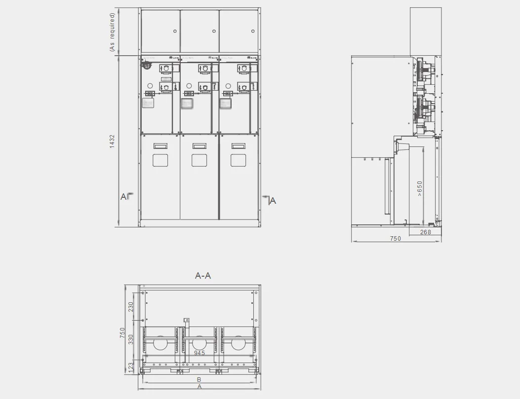
| Unit | Unit 1 | Unit 2 | Unit 3 | Unit 4 | Unit 5 | Unit 6 |
| A | 373 | 698 | 1023 | 1348 | 1673 | 1998 |
| B | 295 | 620 | 945 | 1270 | 1595 | 1920 |


