From transformers and switchgear to ring main units, substations, circuit breakers and smart components, Jubang provides integrated product support for power distribution projects.
Discover Jubang’s strengths in technology R&D, quality testing and smart manufacturing, supporting reliable electrical equipment and efficient power distribution solutions for global customers.
From technical consultation and OEM/ODM customization to EPC support, smart O&M, delivery documentation and after-sales service, Jubang supports your project at every stage.
Explore Jubang Group’s development history, intelligent manufacturing base, R&D platforms, CNAS-accredited laboratory and global project service capabilities.
How to Plan RMU Expansion Without Rebuilding the Distribution Network
Release Time: 2026-08-01
RMU expansion planning decides, at the first RFQ, whether a distribution network can grow by adding modules — or only by replacing switchgear. Extensible ring main units carry design provisions for adding switch, breaker, or fuse ways after installation. Spare ways bank tomorrow’s feeder in today’s enclosure. A non-extensible unit, by contrast, is fixed at its installed configuration, so every later feeder becomes a parallel unit or a rebuild.
None of these mechanisms is free, and none is always right. The planning job is to price growth honestly: what does an extension provision cost now, what does a rebuild cost later, and which network data make that comparison real instead of rhetorical?
Part 1. Why does RMU expansion planning start at the first RFQ?
Ring networks rarely stay the size they were commissioned at. A practitioner thread describing a real oil-field distribution scheme talks about four rings of roughly eight ring main units each, spread over tens of kilometres — a scale nobody reaches in one construction season. Loads appear, sites densify, and each new connection needs a way in some unit somewhere.
The operational purpose of the ring compounds the pressure. Ring main switches exist so that cable sections can be isolated and adjacent feeders interconnected, as the practical guide to ring main unit operation explains; a growth plan that leaves no spare switching capacity slowly erodes exactly that flexibility. Choosing the units is covered in the high voltage ring main unit selection guide — this article covers the property that selection guides often skip: whether the chosen unit can grow.
Buyers who skip the question pay for it in one of three ways later: a premature replacement, a second unit squeezed into a site never sized for it, or an outage-heavy reconfiguration. All three are avoidable with data that exists at RFQ time.
Part 2. Extensible or non-extensible: what actually differs?
The two concepts are defined cleanly in a published technical comparison of extensible and non-extensible ring main units: a non-extensible RMU is a fixed-configuration unit with no module expansion possible after installation, while an extensible RMU is designed with provisions for future extension by adding modules — switch, breaker, or fuse ways — as requirements grow.
Criterion
Non-extensible RMU
Extensible RMU
Configuration after installation
Fixed; the installed ways are the final ways
Extendable by adding functional modules
Typical application
Stable, known loads; space-constrained sites
Industrial parks, campuses, growing networks
Initial investment
Lower
Higher, paying for extension provisions
Footprint
Most compact
Larger, reserving room for added modules
Wrong-choice risk
Growth forces a rebuild or parallel unit
Paid-for provisions may go unused
A peer-reviewed review of ring main unit designs adds the third category between the extremes: modular units whose customizable modules can be configured — and reconfigured — to specific operational needs, an approach it associates with networks that anticipate change.
The table’s last row deserves the most attention. Extensibility is not automatically virtuous; it is an insurance premium. The premium is justified by credible growth scenarios, not by habit.
Part 3. Spare ways: buying tomorrow’s feeder today
Between “fixed forever” and “extendable later” sits the simplest mechanism: order the unit with more ways than today’s network needs. A spare way is a fully built switching function waiting for a cable — no later factory work, no extension module, just a reserved connection point.
What a spare way buys, and what it costs
Buys: the fastest possible feeder addition — terminate the new cable, commission the way, done. No enclosure work, no gas-compartment intervention, no second unit.
Buys: insulation from extension-availability risk years later, because the capacity already exists on site.
Costs: the way itself, plus the footprint of a larger unit from day one — the same footprint trade the extensible-vs-compact comparison highlights.
Costs: discipline. A spare way only stays useful if its interface data (bushing type, connector class, compartment space) was specified with the same care as the active ways — the subject of the companion cable-interface data article in this cluster.
The decision input is a load forecast per node, even a rough one. One or two credible future feeders at a node argue for spare ways there; purely speculative growth argues for extensible construction at key nodes instead, because the premium is deferred until the growth is real.
Part 4. Extension or a second unit: how practitioners decide
When a node finally outgrows its unit, two paths compete: extend the existing unit (if it was bought extensible) or place a second unit beside it. Practitioner experience in the engineering-forum discussion of extensible ring main units is refreshingly concrete about when each path wins: extensible units earn their keep when the future network structure is unknown but one to three additional feeders are expected, and when the required feeder count exceeds what one compact unit offers — because connecting two fixed units loses ways to the interconnection itself, while one unit plus extensions is normally cheaper.
Situation at the node
Path that usually wins
Why
One to three more feeders expected, timing unknown
Extensible unit bought up front
Provisions cost less than a second unit and keep one busbar
Feeder need exceeds one unit’s maximum way count
One unit plus extension modules
Two interconnected fixed units sacrifice ways to the tie
Growth arrived but the installed unit is non-extensible
Second unit, carefully interfaced
The only path left; expect tie losses and civil work
No credible growth scenario
Compact non-extensible unit
Paying an insurance premium with no insurable risk
Treat the table as decision framing, not arithmetic. Each case ends in a quotation comparison — extension modules, second unit, civil works, and outage costs priced against each other for the actual node. The forum’s contribution is the checklist of scenarios; the project’s numbers decide.
Part 5. Modular line-ups versus compact sealed units
Zoom out from single nodes and a spectrum appears. At one end sit compact sealed gas-insulated RMUs — minimal footprint, fixed purpose. At the other end sits air-insulated secondary switchgear, which the overview of ring main units in secondary substations describes as quite freely extendable and configurable. Between them, modular and extensible RMU families trade some compactness for staged growth.
Insulation technology shapes where a product family sits on that spectrum. Sealed SF6-insulated blocks are inherently fixed at their manufactured way count unless the design provides extension interfaces; solid-insulated and air-insulated constructions lend themselves more naturally to module-by-module growth. That is context, not a verdict — a solid-insulated family’s role in medium-voltage distribution is covered in the solid insulated ring cabinet overview, and any specific unit’s extension capability is a property of the offered design, to be confirmed in writing.
For planning purposes, ask one question per node class: does this node need a compact sealed block, a modular line-up, or something in between — and does the answer change within the planning horizon? Nodes near planned development zones justify flexibility; stable residential nodes rarely do.
Part 6. Keeping the ring operable while the network grows
Expansion is not only a hardware question. Every added way and every added unit changes how the ring is switched, sectionalised, and restored — and the growth plan must preserve those operations, not just the feeder count.
Three planning rules keep growth safe:
Stay inside the assembly framework. Extensions and added modules are design provisions of a metal-enclosed switchgear assembly under IEC 62271-200, not field improvisations; the offered design defines what may be added, where, and how.
Preserve sectionalising logic. Each growth step must keep fault isolation and back-feed paths workable — the ring’s reason for existing. Update the switching plan and operator documentation with every added way, using the ring-node context of units like the GT-SRM-12 SF6 gas insulated ring main unit as the reference for what each node contributes.
Re-run the network study at defined thresholds. Added feeders and cable length change load flow and fault behaviour; the study — not the article — owns those conclusions. Agree in advance which growth increments trigger a re-study.
An expansion plan that covers hardware, operations, and study responsibilities survives contact with reality. One that only counts ways does not.
Part 7. RMU expansion planning RFQ checklist
Growth intentions only bind when they are written into the RFQ. This checklist turns the plan into supplier-answerable data.
RFQ input list
System voltage, network topology (ring, open ring, radial with ring provision), and the node classes being purchased.
Current way schedule per node: ring ways, transformer or feeder ways, and their duties.
Credible growth scenarios per node: how many additional feeders, on what horizon, with what confidence.
The growth mechanism requested per node: extensible construction, spare ways, planned parallel unit — or the supplier’s proposal with reasoning.
Footprint and civil constraints per site, including reserved space for extension modules or future units.
Insulation-technology preferences only where a project reason exists (space, environment, service practice) — stated as preferences, not assumed capabilities.
Cable interface data per way, current and future, so spare and extension ways are terminable when their day comes.
Operational constraints for any future extension work: acceptable outage windows, sectionalising plan, and which parts of the ring must stay live.
Network-study responsibilities and the growth thresholds that trigger a re-study.
Documentation set: offered way configuration, extension provisions and their conditions, drawings, and operating instructions.
Commercial data: staging options, spares policy, and the technical contact for growth-plan questions.
Part 8. Which JUBANG equipment fits a growth plan?
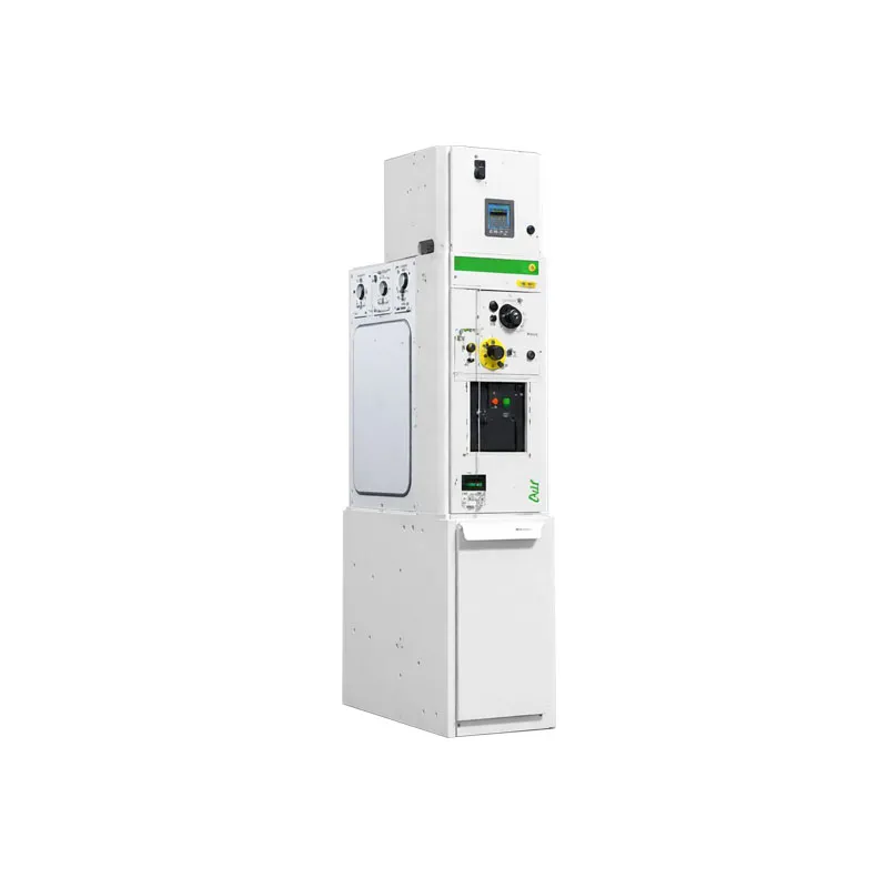
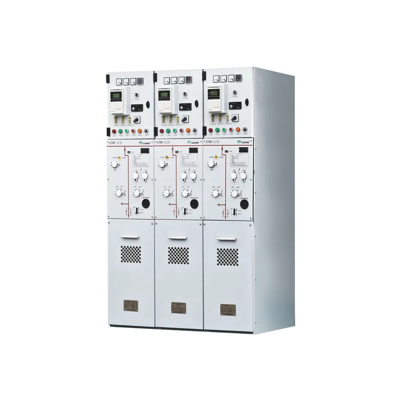
Growth planning lands on product pages once node classes are defined. For compact nodes where modular, solid-insulated construction aligns with staged growth, the GTRM-12 solid insulated ring main unit page is the starting point. For street-level ring nodes that aggregate several ways in an outdoor enclosure, the XGW□-12 box-type switching substation (ring main box) page addresses that duty. Indoor withdrawable metal-clad line-ups are deliberately not recommended here: they serve primary-substation feeder duties, which is a different growth conversation than distributed ring nodes.
Fit Boundary
A good fit: utilities, industrial-park and campus owners, and EPC contractors who hold credible growth scenarios and network data and want way configuration and staging confirmed against specific units.
Not the right path: fixed-load sites where a compact non-extensible unit is the economical answer, and primary-substation feeder line-ups better served by withdrawable switchgear.
Confirm first: the offered way configuration, extension provisions and their conditions, footprint reservations, and the documentation list — all in writing from the offered design.
This article assigns no way count, extension capability, dimension, or compliance status to any JUBANG product; the offered design’s documentation and the project’s network study govern those values.
Next step:send the growth plan and way schedule — node classes, current and future ways, siting constraints, and documentation expectations — and request the offered configuration and extension provisions for your distribution network.
FAQ
What is an extensible ring main unit?
A ring main unit designed with provisions for future extension: additional switch, breaker, or fuse modules can be added after installation, within the conditions the offered design defines.
What is the difference between extensible and non-extensible RMUs?
A non-extensible unit is fixed at its installed configuration — no module expansion afterwards. An extensible unit accepts added modules later, at the price of higher initial cost and a larger footprint.
How can a distribution network add feeders without replacing switchgear?
Three mechanisms, chosen per node: buy extensible units where growth is credible, order spare ways where specific feeders are foreseen, and reserve space for planned parallel units where growth exceeds one enclosure.
Are spare ways cheaper than extending an RMU later?
A spare way avoids later extension work entirely, but you pay for the way and its footprint from day one. Extension provisions defer cost until growth is real. A quotation comparison against the node’s forecast decides.
When is a second RMU better than extending an existing one?
Mainly when the installed unit is non-extensible, or when the site layout favours a new position. Practitioners note that interconnecting two fixed units costs ways at the tie, which is why one unit plus extensions is often the cheaper route where it is available.
What data should an RFQ include for future RMU expansion?
Node-by-node way schedules, growth scenarios and horizons, the requested growth mechanism, footprint reservations, cable interface data for future ways, outage constraints for extension work, and the documentation that records the offered extension provisions.
Does an extensible RMU need more space?
Typically yes — the extension provisions and future modules claim footprint from day one. Site plans should reserve that space explicitly, or the extensibility exists only on paper.
How do modular RMU line-ups differ from compact sealed units?
Compact sealed units fix their ways at manufacture and win on footprint; modular line-ups assemble and reconfigure functional modules and win on adaptability. Air-insulated secondary switchgear extends most freely of all, at the largest footprint.
Products are exported to more than 100 countries and regions such as Africa, the Middle East, and the United Kingdom and Europe. It is a leading manufacturer of power distribution equipment in China.

 JUBANG