From transformers and switchgear to ring main units, substations, circuit breakers and smart components, Jubang provides integrated product support for power distribution projects.
Discover Jubang’s strengths in technology R&D, quality testing and smart manufacturing, supporting reliable electrical equipment and efficient power distribution solutions for global customers.
From technical consultation and OEM/ODM customization to EPC support, smart O&M, delivery documentation and after-sales service, Jubang supports your project at every stage.
Explore Jubang Group’s development history, intelligent manufacturing base, R&D platforms, CNAS-accredited laboratory and global project service capabilities.
Current Transformer Selection Starts With the Project Handoff
Release Time: 2026-08-12
A current transformer selection often stalls for a simple reason: the project has a ratio note, but not an agreed record of what the secondary circuit must do or who confirms it. A meter owner, a protection engineer, and a switchgear supplier can all be looking at the same one-line diagram while working from different assumptions.
Use this guide as a project handoff. It does not prescribe a CT rating, class, burden, or protection performance. Instead, it helps the team collect the right evidence before those project-specific decisions are confirmed.
For the wider equipment context, see JUBANG’s switchgear and ring main unit range. A switchgear route does not by itself establish a standalone CT product offering or a project-fit selection.
1. Start with the missing handoff, not the CT label
Before asking for a class or ratio, identify the decision that is still open. Is the secondary signal intended for a meter or analyser, a protective relay, or separately specified functions? Is the connected circuit known? Has the protection engineer issued the relevant study inputs?
This changes the conversation from “which CT should we use?” to “which project party owns the information that makes the CT requirement valid?” A label copied from an earlier drawing is not a substitute for that answer.
2. Classify the circuit before combining requirements
The first controlled record should state the circuit function in plain language:
Circuit purpose
Decision owner to identify
Evidence that must be named
What must not be assumed
Metering or monitoring
Meter, analyser, or billing-system owner
Receiving device and required measurement condition
That a protection requirement also covers measurement performance
Protection
Protection engineer
Relay function, study reference, and applicable design condition
That a generic protection marking completes the study
Both functions
Engineering coordinator
The approved arrangement and each function’s separate evidence
That one shared label resolves both jobs
The Eastron guide to CT selection for electrical measurement likewise begins with the application before discussing ratio, accuracy, burden, installation, and testing. That sequence is useful vocabulary; the final project requirement must still be tied to the applicable equipment and standard.
3. Build two evidence packs, then join them
Do not send one mixed list of CT terms to the supplier. Assemble two small, traceable evidence packs and join them only in the approved project record.
Metering and monitoring pack
Record the primary circuit reference, expected operating range, system frequency, applicable project standard, receiving meter or analyser, and the complete secondary connection path. Capture the terminals, wiring route, test switches, and every connected device so the connected secondary burden can be established from the real circuit rather than inferred from a nameplate.
Protection pack
Record the relay function, relay input, fault-study reference, protection-study owner, relevant fault cases, and the full secondary circuit. The SEL paper on sizing CTs for line protection describes how connected burden, fault-current characteristics, remanence, and the specific relay application affect protection evaluation. That is why a class marking alone should not be treated as a complete protection requirement.
4. Review the joined record at the switchgear interface
Once both evidence packs exist, the coordinator should submit them with the one-line diagram and equipment schedule. The review should preserve:
the primary circuit name and drawing reference;
the declared metering, monitoring, and protection functions;
the named meter, analyser, relay, terminals, test equipment, and secondary wiring path;
the project standard and the owner of each open engineering decision;
the protection-study and fault-study references where protection is involved; and
the required drawings, factory documents, and review or witness points.
This record gives the switchgear supplier a controlled basis to review the integrated scheme. It does not replace the electrical study or transfer the protection engineer’s approval to the supplier.
Put the CT Record Into the Switchgear Review
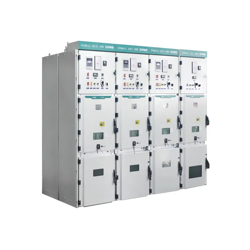
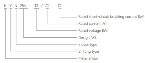
JUBANG’s KYN28A-12 Metal Clad Switchgear page lists current-transformer components within several primary-wiring and metering schemes. Where this is the proposed switchgear route, provide the complete CT handoff together with the primary scheme so the integrated configuration can be reviewed.
The page does not establish that every KYN28A-12 scheme includes a particular CT, that JUBANG sells CTs as standalone products, or that a listed component is suitable for a particular project. Final configuration remains subject to the approved one-line diagram, engineering studies, governing requirements, and supplier confirmation.
Products are exported to more than 100 countries and regions such as Africa, the Middle East, and the United Kingdom and Europe. It is a leading manufacturer of power distribution equipment in China.

 JUBANG