From transformers and switchgear to ring main units, substations, circuit breakers and smart components, Jubang provides integrated product support for power distribution projects.
Discover Jubang’s strengths in technology R&D, quality testing and smart manufacturing, supporting reliable electrical equipment and efficient power distribution solutions for global customers.
From technical consultation and OEM/ODM customization to EPC support, smart O&M, delivery documentation and after-sales service, Jubang supports your project at every stage.
Explore Jubang Group’s development history, intelligent manufacturing base, R&D platforms, CNAS-accredited laboratory and global project service capabilities.
Power Factor Explained: kW, kVA and What Low PF Changes
Release Time: 2026-11-11
Power factor is the ratio of real power to apparent power: PF = P / S, commonly written as kW / kVA. For the same real load and supply voltage, a lower power factor means a higher apparent-power and current requirement. It is not a direct percentage of energy wasted.
The familiar expression cosφ describes the displacement relationship between sinusoidal voltage and current. When waveform distortion matters, distinguish that fundamental-frequency relationship from true power factor.
What kW, kVA and power factor describe
Real power P, expressed in kW, describes the average power transferred to the load. Apparent power S, expressed in kVA, describes the voltage-current loading. Their ratio is power factor. The units are related, but they answer different questions.
For a consuming-load example with positive values, kVA = kW / PF. If 100 kW corresponds to 125 kVA, the power factor is 100 / 125 = 0.8. The calculation does not say that only 80% of the electricity bill performs useful work, nor does it establish an equipment efficiency.
Meter sign conventions are another detail to preserve. A signed PF display needs to be interpreted using that meter’s convention. The positive examples here do not diagnose power-flow direction from an unexplained sign.
True PF and displacement PF are not interchangeable
Displacement power factor concerns the phase relationship at the fundamental frequency. For sinusoidal voltage and current, the familiar cosφ interpretation applies. True power factor accounts for harmonic content as well.
A meter reading therefore needs a definition, not just the label “PF.” A near-unity displacement value does not by itself establish the same true PF when current is distorted. Conversely, a low displayed value cannot identify the cause without knowing which quantity the meter reports.
This distinction matters before discussing correction. The required investigation depends on the load and measured waveform conditions. A generic capacitor recommendation cannot be derived from an unspecified PF number.
Worked example: the same 100 kW at different PF
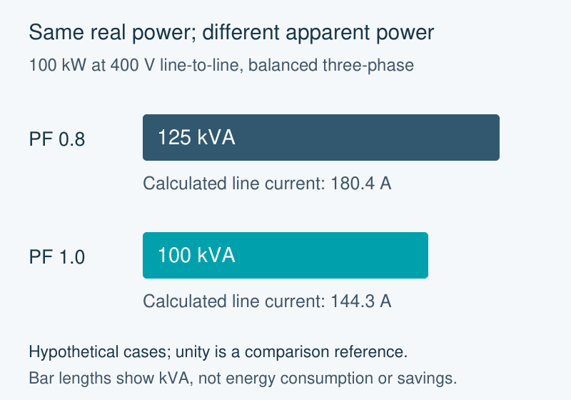
Assume two hypothetical balanced, sinusoidal three-phase cases at 400 V line-to-line, each transferring 100 kW. One has PF 0.8; the other has unity PF. Unity is an arithmetic reference here, not a recommended project target or a measured correction result.
Using S = P / PF and IL = 1000 × S(kVA) / (√3 × VLL) gives:
Assumed PF
Apparent power
Calculated line current
0.8
100 / 0.8 = 125 kVA
125,000 / (√3 × 400) = 180.4 A
1.0
100 / 1.0 = 100 kVA
100,000 / (√3 × 400) = 144.3 A
Original same-load calculation. Bar lengths compare total kVA, not kW plus kVAr and not energy consumption. Real power remains 100 kW in both cases.
The lower-PF case needs more current to transfer the same assumed real power at the same voltage. That is the capacity consequence illustrated by the calculation. If the voltage, load or waveform basis changes, it is a different comparison and needs its own inputs.
Why the difference is not a savings percentage
The example changes apparent power and current while deliberately holding real power constant. It does not calculate energy use over time, network losses, correction-equipment losses or a utility tariff. Subtracting the two kVA values therefore does not produce a kWh saving.
It also does not select a transformer, cable or protective device. Those decisions need the full load and operating conditions. PF is one input to understanding the distribution duty, rather than a shortcut around the rest of the design.
Keep a capacity claim and an energy claim separate when reviewing an offer. A supplier should identify what its stated improvement measures, the operating conditions and the evidence behind the comparison. A before/after percentage without those definitions is difficult to evaluate.
Record the measurement context before choosing an action
A useful PF record identifies the measurement location, time interval, operating state, kW, kVA and whether the reported PF is true or displacement. Include the relevant harmonic information when electronic loads make waveform distortion part of the question.
Use readings from the same operating case when comparing values. A lightly loaded period and a production peak may describe different demand and load mixes. Combining their numbers can create an apparently precise ratio that never represented an actual operating state.
JUBANG’s published BlokSeT LV power-distribution and motor-control equipment provides a business connection for discussing the resulting distribution requirements. This does not establish a JUBANG capacitor-bank, harmonic-filter or PF-audit offering. Any equipment discussion should start from the defined load and measurement context.
Products are exported to more than 100 countries and regions such as Africa, the Middle East, and the United Kingdom and Europe. It is a leading manufacturer of power distribution equipment in China.

 JUBANG