From transformers and switchgear to ring main units, substations, circuit breakers and smart components, Jubang provides integrated product support for power distribution projects.
Discover Jubang’s strengths in technology R&D, quality testing and smart manufacturing, supporting reliable electrical equipment and efficient power distribution solutions for global customers.
From technical consultation and OEM/ODM customization to EPC support, smart O&M, delivery documentation and after-sales service, Jubang supports your project at every stage.
Explore Jubang Group’s development history, intelligent manufacturing base, R&D platforms, CNAS-accredited laboratory and global project service capabilities.
BESS Booster Substation Protection: Interfaces to Clarify Before Ordering
Release Time: 2026-07-22
Booster substation protection for a battery energy storage system (BESS) spans four interfaces: the power conversion system, the step-up transformer, the MV switchgear and the grid connection. Ordering the substation before those interfaces carry named data and named owners is how projects end up with nuisance trips, earthing surprises and unassigned signals during commissioning.
This checklist walks through each interface — what to hand the supplier, what to request back, and which decisions stay with the project’s protection engineer rather than with any equipment vendor.
Part 1. What booster substation protection covers
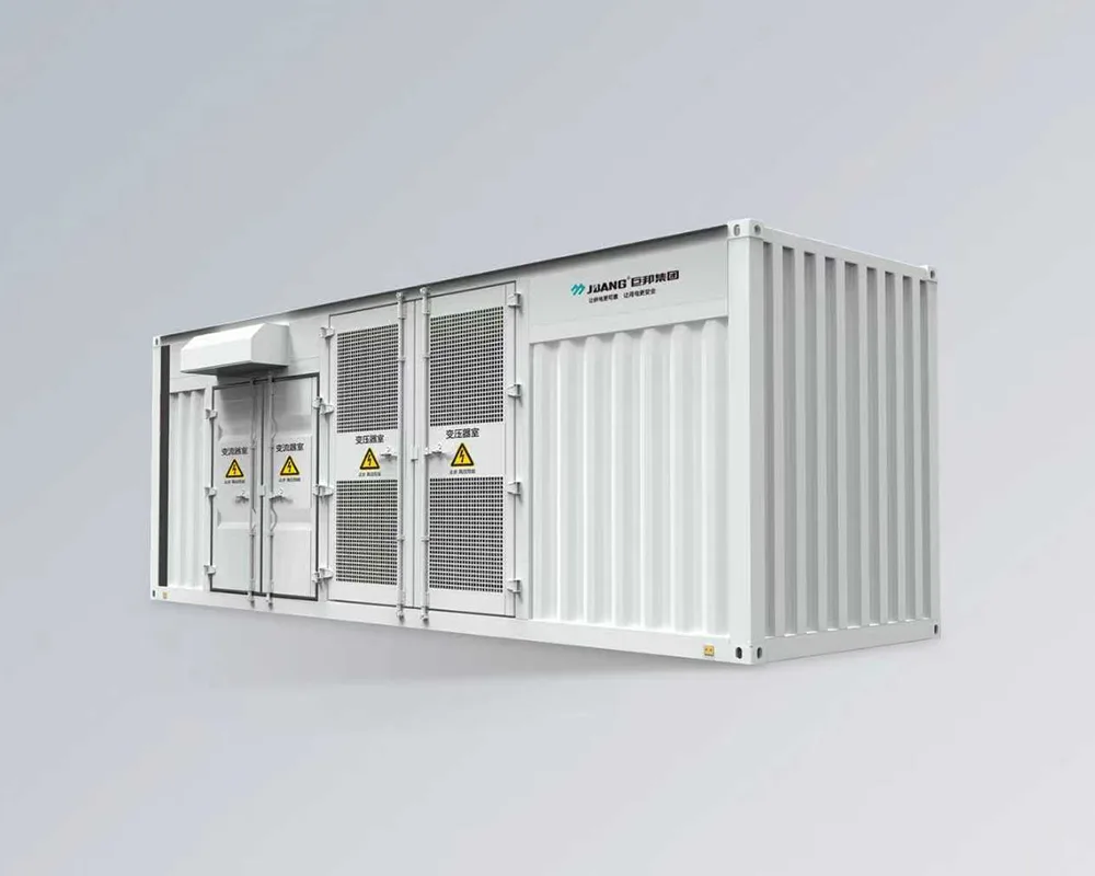
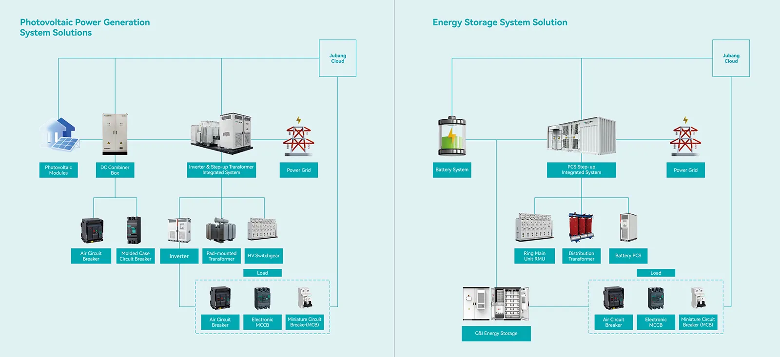
A BESS booster substation takes the output of one or more power conversion system units and steps it up to the medium-voltage network, usually as a factory-integrated unit from a prefabricated substation family. Its protection scope therefore sits between two systems engineered by other parties: the storage supplier’s converter and battery management side, and the network operator’s grid side.
System-level safety for grid-integrated electrochemical storage is the subject of IEC 62933-5-2:2025, which addresses the whole BESS life cycle and builds on the general provisions of its companion part. Battery-rack and cell-level protection stays inside the storage supplier’s scope; the booster substation order is about the electrical interfaces around the step-up path.
Part 2. Converter handover data the supplier needs
Converter documentation leads the interface work because the converter OEM can impose model-specific requirements on the transformer connected to it. The SMA medium-voltage transformer requirements are a public example: winding voltage matching, attention to converter operating behaviour and the system grounding context all come from the converter side, not from a catalogue.
Handover item
Why the booster substation supplier needs it
Common gap
Converter model documentation
Carries the OEM’s transformer and interface requirements
Buyer sends a family brochure instead of the applicable document
Number of converter units per substation
Decides winding arrangement questions and switching scope
Assumed one-to-one when the plant layout says otherwise
Converter earthing and neutral expectations
Shapes the transformer vector group discussion and fault behaviour
Left implicit until commissioning
Operating modes (charge, discharge, standby)
Protection must stay stable across reversing power flow
Only the discharge case is communicated
Converter protection functions already present
Avoids duplicated or conflicting tripping
Nobody lists what the converter already trips on
A related data-handover discussion for solar projects is in PV booster station design inputs; the storage case adds reversing power flow and the storage supplier’s own protection layer.
Tip: Ask the converter supplier for the exact interface-requirements document for the quoted converter model, and attach it to the substation RFQ — the practice mirrors converter OEM guidance such as the SMA transformer requirements.
Part 3. Step-up transformer devices and signals
The step-up transformer inside the booster unit belongs to the power-transformer standards family identified by the IEC 60076 listing, and its protective devices depend on the supplied model and configuration. Do not assume a device list; request it.
Ask the supplier to confirm, from current model documentation:
which winding temperature indication or monitoring the quoted transformer carries, and what contacts it provides;
whether a Buchholz relay applies to the supplied liquid-filled arrangement, and its alarm and trip contacts;
whether a pressure relief device is fitted and how its operation is signalled;
liquid level and any other condition devices, with their contact ratings; and
which of those contacts are wired to terminals, and where the terminal schedule sits in the drawings.
Every confirmed device becomes a row in the project signal list with an agreed alarm or trip action. A device that exists but is not wired into the protection logic is a finding, not a feature.
Part 4. Relays and instrument transformer inputs
Protection functions need measurements, so relays, current transformer and voltage transformer provisions must be resolved together. Relay vendor documentation — the SEL-787 transformer protection relay pages are one example of the class — defines which functions are available and which measurement inputs each function expects.
Question to resolve before ordering
Who answers it
Which protection functions live inside the booster substation, and which at the grid connection point?
Project protection engineer with the network operator
Which current transformer cores, ratios and accuracy classes do those functions require?
Protection engineer; supplier confirms what the unit can carry
Is a voltage transformer required inside the unit for the intended functions?
Protection engineer; supplier confirms provisions
Which relay platform does the operator standardize on, if any?
Owner/operator
Who supplies, wires and tests the relays — the substation factory or a systems integrator?
Named in the contract scope table
Function-by-function coordination questions for the transformer itself are covered in transformer protection relays: functions, inputs and coordination boundaries. Keep that engineering with the protection authority; the equipment order only has to make the required measurements and wiring physically possible.
Part 5. Earthing and enclosure interfaces
Earthing decisions produce the ugliest surprises because they sit exactly between parties. Field reports on storage feeders tripping on ground fault frequently trace back to neutral bonding points and measurement arrangements that no one had reviewed as a system — user discussions on engineering forums describe repeated trips cured only after the bonding scheme was re-examined.
Resolve before ordering:
The intended earthing arrangement across converter, transformer windings and MV network, stated by the project protection authority.
The transformer vector group question that follows from it — a converter OEM’s grounding-context requirements and the network’s expectations must both be satisfied.
Where neutral connections, earthing terminals and any earthing accessories physically sit in the enclosure, and who connects them to the site earthing grid.
How enclosure-level requirements are stated: booster substations delivered as prefabricated assemblies fall under the stated scope of IEC 62271-202:2022, so classifications for the enclosure are requested and confirmed the same way as for any prefabricated substation.
None of this fixes values in an article. The point is allocation: each item above needs an owner and a document reference in the order.
Part 6. Signal matrix, SCADA and responsibility boundaries
Protection only completes when signals reach the party that must act on them. A small responsibility table in the tender prevents the classic commissioning scramble:
Interface
Typical supplier side
Typical project side
Transformer device contacts
Wired to terminals per model documentation
Mapped into trip matrix and SCADA
Relay trip and alarm outputs
Functions and outputs as configured at the factory
Settings, testing and acceptance by the protection authority
Remote signals to the operator
Protocol capability of the supplied devices
Signal list, communications path, point database
Trip authority between converter and substation
Documented interlocks as ordered
Operating philosophy and switching authority
Fit boundary: this article suits buyers coordinating a BESS booster substation order who need to route protection data and responsibilities before the purchase. It is not a protection study, a settings calculation, an earthing design or a grid-code interpretation — those belong to the responsible project protection authority and the network operator. If the project cannot yet name a protection authority, resolve that before ordering equipment.
Both are product-family starting points, not selections; suitability depends on the converter documentation, earthing decision, grid requirements and current JUBANG documentation. PV and wind combined-transformer variants are deliberately not recommended for this scope, because their interface data follows solar inverters and wind turbine converters rather than storage power conversion systems.
Send these inputs with the RFQ:
Storage system one-line diagram and the converter documentation, including its transformer and grounding requirements.
Number of converter units per booster substation and the winding-arrangement question to be resolved.
Grid connection data as available: voltage level, intended earthing arrangement, applicable grid requirements, fault-data status.
The protection philosophy owner, and which functions are expected inside the unit versus at the grid interface.
Transformer devices and signals to be confirmed from model documentation.
SCADA and communication expectations: draft signal list, required protocols, remote trip and alarm routing.
Documents and tests: type test evidence, routine tests, factory acceptance test witnessing, protection interface drawings, as-built documentation.
Submit the package through the online message form for a configuration review against current product documentation.
FAQ
What is a BESS booster substation?
A factory-integrated substation that steps the output of a battery energy storage system’s power conversion equipment up to the medium-voltage network. It typically combines the step-up transformer, MV switching and auxiliary systems in one transportable enclosure.
Does a battery energy storage system need a step-up transformer?
Grid-connected storage at medium voltage generally reaches the network through a transformer, and some converter suppliers additionally require an interface transformer for earthing or operating reasons. The applicable converter documentation and the project’s electrical design answer the question for a specific plant.
Who sets the protection settings for a BESS booster substation?
The responsible project protection authority, in coordination with the network operator. Equipment suppliers provide device data, wiring and factory-configured functions within their documented scope; they do not own the coordination study or the settings.
Why does a BESS breaker trip on ground fault?
Field discussions repeatedly point to system-level causes: neutral bonding in more than one place, measurement arrangements that see load or circulating current as residual current, or protection expectations that ignore an earthing decision. The cure is a system review by the protection authority, not a device swap.
What protection devices does a storage step-up transformer carry?
It depends on the supplied model and configuration. Winding temperature devices, a Buchholz relay on applicable liquid-filled arrangements and a pressure relief device are common candidates — confirm the actual list, contacts and wiring from the model documentation rather than assuming.
Can one booster substation serve several converter units?
Plant layouts do connect multiple converter units to one step-up path in some designs. The answer for a given project comes from the plant electrical design, the converter documentation and the winding-arrangement review; state the intended grouping in the RFQ so the supplier quotes the right configuration.
What should a BESS booster substation RFQ include?
The one-line diagram, converter documentation, converter count and grouping, grid connection data, the protection philosophy owner, the transformer device and signal expectations, SCADA requirements, the document-and-test list, and commercial data such as quantity, delivery location and terms.
Products are exported to more than 100 countries and regions such as Africa, the Middle East, and the United Kingdom and Europe. It is a leading manufacturer of power distribution equipment in China.

 JUBANG