From transformers and switchgear to ring main units, substations, circuit breakers and smart components, Jubang provides integrated product support for power distribution projects.
Discover Jubang’s strengths in technology R&D, quality testing and smart manufacturing, supporting reliable electrical equipment and efficient power distribution solutions for global customers.
From technical consultation and OEM/ODM customization to EPC support, smart O&M, delivery documentation and after-sales service, Jubang supports your project at every stage.
Explore Jubang Group’s development history, intelligent manufacturing base, R&D platforms, CNAS-accredited laboratory and global project service capabilities.
Electrical Switchgear: Main Components, Voltage Classes and How It Works
Release Time: 2026-11-06
Electrical switchgear is an assembly that switches, protects and controls electrical power. It brings together switching devices, conductors and their supporting control and protection equipment. The cabinet is the visible enclosure; the useful system is the coordinated equipment inside it.
A circuit breaker is therefore a component of switchgear, not a complete description of it. Two assemblies can contain similar breakers yet differ in bus arrangement, fault duty, access and operating provisions. Those differences matter when an engineer specifies equipment or a buyer compares quotations.
What electrical switchgear does
Switchgear performs three related functions: protection, isolation and switching. Protection responds to abnormal electrical conditions. Switching establishes or interrupts a circuit during its intended operation. Isolation provides a defined separation for work on equipment, subject to the device design and the site’s safety procedures.
These functions should appear separately in a specification. A device that switches a load does not automatically provide every protective function. Likewise, an “open” indication is not, by itself, proof that a complete installation is isolated. The project must identify the devices and provisions that perform each duty.
This functional view also explains why metering, control power and operating interfaces belong in an equipment review. They help the operator understand and command the power system, even though they do not all carry the main load current.
How power moves through switchgear
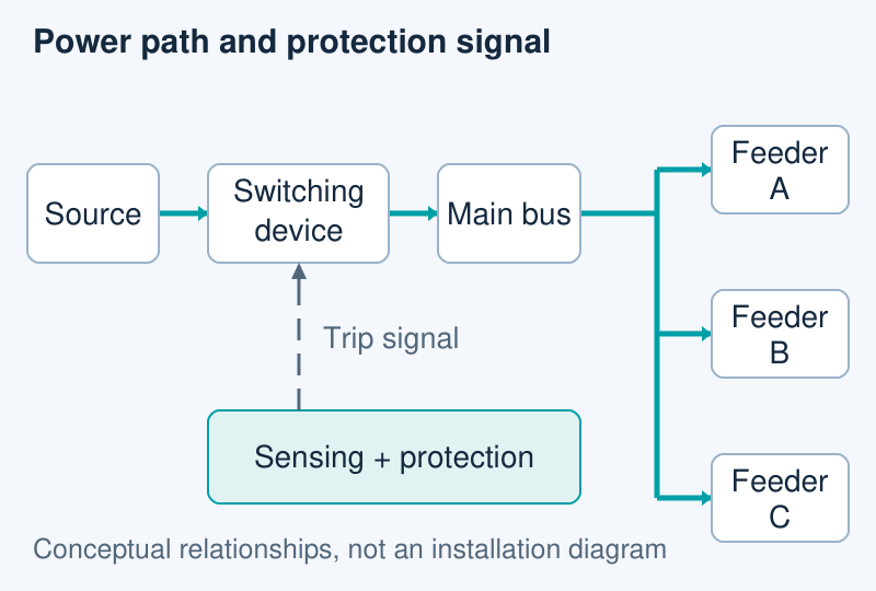
In a simple distribution arrangement, an incoming circuit connects the supply to a main bus. The bus distributes power to outgoing feeder circuits. Each feeder then serves a downstream load or another distribution assembly. The actual arrangement may include multiple sources or bus sections, so the project one-line diagram remains the reference.
The protection path is different from the power path. Sensing and protection logic identify the relevant electrical condition and initiate the opening action. Depending on the equipment, these functions may be integrated into a breaker or distributed between separate devices. Reading the two paths separately helps prevent a missing control or protection interface from disappearing inside a generic “switchgear” line item.
Conceptual relationships only. The solid paths represent power distribution; the separate signal path represents a protection command. This is not an installation or switching diagram.
Main components and the questions they answer
A useful component review connects each physical part to a system question and a document. The following map is a reading aid rather than a mandatory parts list for every switchgear design.
Component or function
Question to resolve
Document to compare
Main and branch bus conductors
Where does power travel between sections and feeders?
One-line diagram and bus arrangement
Switching and interrupting devices
Which device establishes or interrupts each circuit?
Device schedule and operating description
Sensing, protection and control
What initiates an opening command, and how is it transmitted?
Protection and control schematic
Cable terminations and connections
Where do incoming and outgoing circuits connect?
Termination and access drawings
Enclosure and internal divisions
How are equipment spaces arranged and accessed?
General arrangement and compartment drawings
A catalogue photograph cannot answer all these questions. For example, it may show a breaker front without showing the cable approach or control interfaces. The comparison becomes meaningful when the physical arrangement and electrical function describe the same configuration.
Voltage class and insulation describe different choices
Voltage class describes the electrical system and equipment rating. Insulation describes how the design separates energized parts from each other and from earth. Air, gas and solid insulation are design families; none is a substitute for checking the equipment’s stated ratings and configuration.
Low-voltage and medium-voltage terminology also needs a defined project context. Exact category boundaries and equipment names depend on the specification and standard being used. A purchasing schedule should state the required rated values and applicable basis rather than rely on the label “MV” or “LV” alone.
Comparing only insulation technology can hide more practical differences. A buyer still needs to understand the switching function, cable interfaces, access arrangement and required documents. The correct comparison is between complete configurations that perform the same project duty.
Three electrical duties that must stay separate
Continuous current, fault interruption and short-time withstand answer different questions. A large current value on a breaker does not establish every rating of the assembly that contains it.
Duty
What it addresses
Comparison mistake to avoid
Continuous current
Carrying the intended operating current under specified conditions
Assuming a device rating establishes the entire bus and assembly rating
Fault interruption
Opening a fault current at the specified electrical conditions
Treating an interrupting value as an ordinary load-current rating
Short-time withstand
Withstanding a specified current for a stated duration under the applicable conditions
Comparing current magnitudes without comparing their associated time
The supplier’s assembly documentation should identify the offered configuration and its ratings. Device documentation then supports the components within that configuration. Keeping these two levels separate makes it easier to locate a mismatch without assuming that one impressive catalogue value settles the whole review.
Compartments and access are part of the arrangement
Internal divisions describe where the equipment sits; access drawings explain how people and cables reach those spaces. Both affect the practical layout. A front elevation alone does not establish whether the project also needs access behind or beside the assembly.
As a product-specific example, JUBANG’s KYN61-40.5 metal-clad switchgear describes separate relay/instrument, circuit-breaker handcart, busbar and cable spaces, divided by earthed metal partitions. This illustrates a particular compartment arrangement. It does not make every cabinet equivalent or establish an internal-arc classification for an unspecified configuration.
The drawing review should connect those spaces to the project’s cable route and access plan. That check belongs beside the electrical schedule, not after the equipment has been selected.
A four-document handover for comparing equipment
Start with the one-line diagram: identify the sources, bus sections and outgoing circuits. Then read the assembly schedule to establish the offered equipment ratings and configuration. These documents explain what the system must do and what the complete assembly is intended to withstand.
Read the device schedule next. Check that the switching, sensing and protection functions correspond to the same circuits and operating description. A component substitution should remain visible at this level rather than disappear inside an unchanged cabinet description.
Finish with the access and termination drawing. Confirm where cables enter, where connections sit and which sides of the assembly require access. Record unresolved differences against the relevant drawing or schedule. The result is a specific technical query the supplier can answer, rather than a request to confirm that the equipment is simply “suitable.”
Products are exported to more than 100 countries and regions such as Africa, the Middle East, and the United Kingdom and Europe. It is a leading manufacturer of power distribution equipment in China.

 JUBANG