From transformers and switchgear to ring main units, substations, circuit breakers and smart components, Jubang provides integrated product support for power distribution projects.
Discover Jubang’s strengths in technology R&D, quality testing and smart manufacturing, supporting reliable electrical equipment and efficient power distribution solutions for global customers.
From technical consultation and OEM/ODM customization to EPC support, smart O&M, delivery documentation and after-sales service, Jubang supports your project at every stage.
Explore Jubang Group’s development history, intelligent manufacturing base, R&D platforms, CNAS-accredited laboratory and global project service capabilities.
Data Center Switchgear: MV/LV Architecture and Procurement Inputs
Release Time: 2026-11-07
Data center switchgear should be specified against the project’s electrical one-line diagram and operating states. The enquiry needs to identify which medium-voltage (MV) and low-voltage (LV) functions belong in the equipment package, how they connect to adjacent systems and what the offered configuration must demonstrate.
A “critical power” description does not settle those questions. A useful purchasing scope connects equipment duties with normal supply, alternative supply, maintenance and expansion conditions. It also separates the power path from the controls and responsibilities needed to operate it.
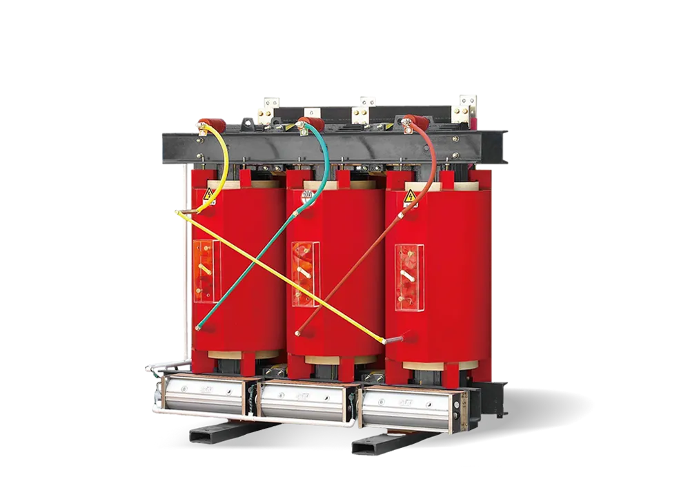
Cover image: conceptual illustration, not an actual JUBANG customer installation.
Where data center switchgear sits in the architecture
A data-center distribution arrangement can include MV switchgear, transformers and LV distribution feeding IT and facility systems. That is a possible arrangement, not a universal sequence for every site. Utility connection levels, source arrangements and UPS locations vary with the project architecture.
The one-line diagram should therefore define the actual boundaries. It should show where each source enters, which equipment forms the MV/LV interface and which downstream systems fall outside the switchgear package. A generic equipment illustration cannot establish redundancy or an availability classification.
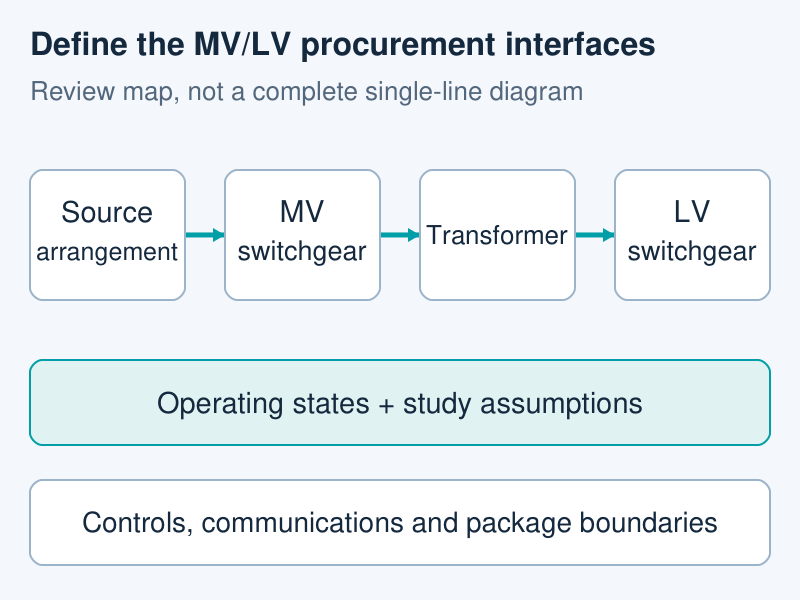
Procurement interface map only. Actual source connections, UPS placement, downstream branches and switching arrangements belong on the project one-line. The lower bands identify review inputs, not additional power circuits.
Start the equipment schedule from those boundaries. This makes it possible to ask whether a supplier is offering an individual lineup, a coordinated equipment package or a broader integration scope. The answer affects the documents and interfaces that must accompany the offer.
Define operating states before comparing cabinet line items
The normal operating diagram is only part of the procurement question. The project team should also identify the other states that the offered equipment is expected to support. The following matrix is a suggested enquiry tool; the design team determines which states are applicable and acceptable.
Operating state
Question to define
Information to request
Normal supply
Which sources, bus sections and loads are in service?
The agreed one-line revision and equipment-duty schedule
Alternative-source operation
Which source arrangement is intended, and which loads must remain supplied?
The operating description, interface responsibilities and relevant study assumptions
Planned maintenance
Which equipment is unavailable, and what service condition must the remaining system support?
The design team’s defined maintenance cases and associated equipment/access information
Phased construction or expansion
Which equipment exists in the initial phase, and which interfaces are reserved for later work?
Phase-specific one-lines, arrangement drawings and extension boundaries
Each row should refer to a stated project case. A general claim that equipment is “redundant” leaves too much unresolved: the buyer still needs to know the intended state, the affected equipment and the documents supporting that condition.
The same discipline helps with changes during tendering. If a source arrangement or construction phase changes, the team can identify which equipment duties and interfaces need review rather than assuming that an unchanged cabinet description remains sufficient.
Connect fault-duty questions to the relevant source case
Ask the design team to identify the study assumptions and equipment duties for each relevant source configuration. The supplier’s offered ratings should then be traceable to that information and to the offered assembly configuration.
This is more useful than requesting a large fault-current number without its context. The enquiry should identify the electrical conditions, applicable duty and configuration being compared. It should not assume that utility supply, an alternative source and a changed bus arrangement create an identical equipment duty.
Protection and control responsibilities also need an owner. The bid should identify who provides the relevant study inputs, operating description and offered protection/control documentation. This article does not prescribe settings or transfer sequences; those decisions belong to the project’s engineering process.
Review physical access and future interfaces together
A phase plan should be reflected in the arrangement information. The buyer needs to understand which parts of the offered lineup are present now, where future interfaces are located and which access requirements belong to the selected configuration.
The practical review connects the general arrangement with the phase-specific one-line. An electrical provision for future equipment does not, by itself, describe the physical space, cable approach or access arrangement needed for that later phase. Those questions should be resolved in the layout documents.
Separate control, communications and package responsibilities
A power connection and a control interface are different deliverables. The enquiry should identify the required signals, operating commands and communications responsibilities without assuming that all integration work is included with the cabinet.
Use an interface schedule that names the sending system, receiving system, required information and responsible party. Where the protocol, control supply or scope is undecided, record it as an open interface question. This gives the supplier a defined issue to resolve rather than a broad request for “smart” or “integrated” equipment.
Build the equipment enquiry around deliverables
A useful enquiry packet combines the current one-line, operating-state matrix, equipment-duty schedule, arrangement drawings and control/interface schedule. The supplier’s response should identify the offered configuration, technical deviations, documents included and responsibilities excluded.
For a JUBANG equipment discussion, the published KYN61 metal-clad switchgear and BlokSeT low-voltage switchgear provide distinct MV and LV product-family starting points. Their catalogue presence does not establish a complete data-center architecture or project approval; the specified duty and interfaces still need review.
Before comparing prices, resolve which operating cases and deliverables each offer covers. A supplier response tied to the same one-line revision and responsibility schedule is far easier to evaluate than a list of cabinets carrying the same application label.
Products are exported to more than 100 countries and regions such as Africa, the Middle East, and the United Kingdom and Europe. It is a leading manufacturer of power distribution equipment in China.

 JUBANG