From transformers and switchgear to ring main units, substations, circuit breakers and smart components, Jubang provides integrated product support for power distribution projects.
Discover Jubang’s strengths in technology R&D, quality testing and smart manufacturing, supporting reliable electrical equipment and efficient power distribution solutions for global customers.
From technical consultation and OEM/ODM customization to EPC support, smart O&M, delivery documentation and after-sales service, Jubang supports your project at every stage.
Explore Jubang Group’s development history, intelligent manufacturing base, R&D platforms, CNAS-accredited laboratory and global project service capabilities.
AC Contactor: How It Works, Main Parts and Motor-Control Ratings
Release Time: 2026-11-06
An alternating current contactor is an electrically controlled switch for an AC load. In a conventional electromagnetic design, a coil moves an armature, and the armature operates the contacts. This lets a control circuit command a separate power circuit, such as a motor feeder.
The important distinction is between the switched load and the control coil. An AC motor load does not automatically require an AC-only coil. The main contacts and the coil have separate ratings, and some electronic coils accept a marked AC/DC supply range. Both sides need to match the application.
How an alternating current contactor works
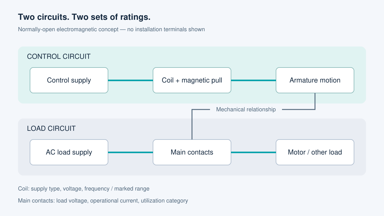
Consider a conventional, non-latching contactor with normally open main contacts. Energizing its coil creates magnetic attraction. The moving armature is drawn toward the magnetic structure and operates the contact mechanism, allowing the main contacts to close.
When the control supply is removed, the return mechanism releases the armature and the contacts open. This describes the basic operating relationship, not the detailed construction of every contactor. Latching devices and electronically controlled designs need their own operating documentation.
The coil does not carry the motor’s main load current. Its job is to operate the mechanism. Keeping this distinction visible in the component schedule prevents a motor-voltage label from being mistaken for the required coil supply.
The control supply operates the coil and mechanism; the main contacts switch the load. Conceptual relationships only, without terminal numbers or installation wiring.
Main contacts, auxiliary contacts and coil
The main contacts establish or interrupt the load path. Their suitability depends on the load voltage, operational current and switching duty. A current value without its associated duty is incomplete selection information.
Auxiliary contacts provide separate control or signaling functions. Their normally open or normally closed arrangement and their own electrical duty need specification. A spare auxiliary contact is not automatically suitable for carrying a power load simply because it belongs to the same contactor.
The coil is the operating input. Its supply type, voltage and frequency where applicable belong in the control-circuit specification. Mechanical fit, accessories and environmental conditions also form part of the complete component selection.
Part
Information to record
What it does not establish
Main contacts
Load voltage, current, number of poles and utilization category
The coil supply or complete feeder protection
Auxiliary contacts
Contact arrangement and the actual signaling/control duty
A main-power switching rating
Coil
AC/DC supply, marked voltage or range, and relevant frequency
The voltage or current that the main contacts can switch
Accessories and mounting
Required interfaces, interlocks and enclosure conditions
Compatibility with an unspecified contactor variant
Why motor duty changes the rating comparison
A utilization category connects a contactor rating to a defined kind of switching duty. AC-1 is associated with non-inductive or slightly inductive loads. AC-3 addresses starting squirrel-cage motors and switching them off during normal running.
Those descriptions explain why the same printed current cannot be moved freely between applications. A resistive load and a motor do not present the same switching duty. The selection must use the manufacturer’s operational rating for the relevant category and voltage.
A motor description should also state how it operates. Normal starting and stopping, repeated jogging and other demanding operating patterns are different application inputs. Rather than assigning a generic category from the word “motor,” the designer should describe the actual duty and check the manufacturer’s applicable selection data.
Read the coil rating independently
The coil marking is the reference for its accepted control supply. Conventional AC coils identify a voltage and relevant frequency. Other variants use DC, while certain electronic coils accept a specified range. The product family name alone does not resolve which version is fitted.
This distinction matters during replacement and during new cabinet specification. A component may have the right main-contact duty but the wrong control input. Conversely, a matching coil supply does not establish that the contacts suit the load. Both checks must remain visible in the offered part number and technical data.
Manufacturer coil codes can help identify a variant, but codes are not universal across brands or ranges. The actual marking and matching documentation should take precedence over assumptions based on a familiar suffix.
The contactor is one part of the motor feeder
Contactor switching duty should be reviewed alongside the feeder’s specified protection and control arrangement. The contactor designation alone does not describe the overload device, short-circuit protective device, interlocks or their coordination. Those are separate items to resolve in the assembly design.
JUBANG’s BlokSeT low-voltage switchgear lists motor control among its application functions. For a motor-control cabinet enquiry, the useful starting point is the feeder duty and control interface, rather than an isolated request for a contactor current rating.
A motor-control data handover
Keep the load, command and assembly information together in the enquiry. The load description should identify the motor application, supply conditions, operating duty and the rating data available for review. The command description should identify the coil supply and the required auxiliary signals.
The assembly description should then identify enclosure conditions, operating frequency, required interlocks and the intended protective arrangement. The supplier can map those inputs to an offered component schedule and control drawing. Where a detail remains unresolved, recording the missing input is more useful than accepting an apparently equivalent contactor based on current alone.
Products are exported to more than 100 countries and regions such as Africa, the Middle East, and the United Kingdom and Europe. It is a leading manufacturer of power distribution equipment in China.

 JUBANG