JUBANG



When a PV EPC manager in Nakhon Ratchasima, Thailand, signed off a 1.6 MVA inverter block, the first energisation test showed hot spots at the low-voltage bus and nuisance trips on the medium-voltage feeder. The visible failure appeared to be a faulty inverter. A joint review found a different root cause: the transformer impedance, cable length and protection settings had been selected independently, while the enclosure ventilation assumption ignored the 42 °C afternoon ambient. Re-matching the inverter, booster transformer and switchgear solved the trip pattern. The lesson for projects in Southeast Asia and the Middle East is that an integrated box substation is an engineered system, not simply three catalogue items placed in one cabinet.
Summary: A European inverter boost integrated box substation combines inverter output, step-up transformer, medium-voltage switchgear, protection and auxiliaries in a factory-assembled enclosure. For a 1,000 kVA block operating 8,000 hours, a 1.0 kW reduction in transformer no-load loss avoids about 8,000 kWh annually before load losses and tariff effects. Specify interfaces, temperature rise, ingress protection and routine/type tests against IEC 62271-200, IEC 62271-1 and IEC 60076 rather than comparing kVA alone. Freeze the load profile, grid code and civil envelope before requesting a firm quotation.
What the European-style package actually integrates
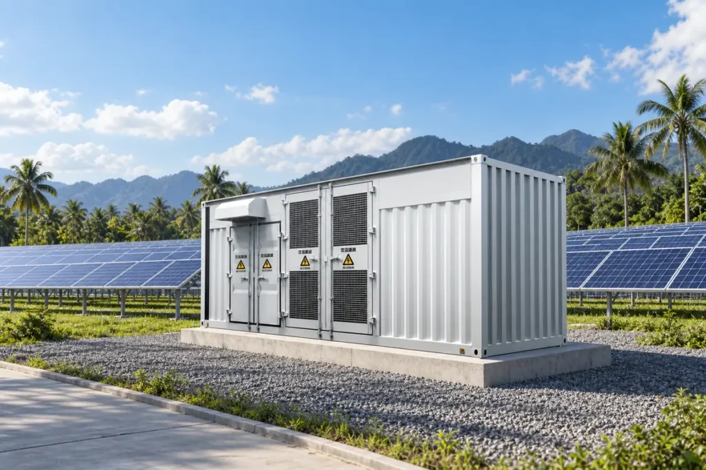
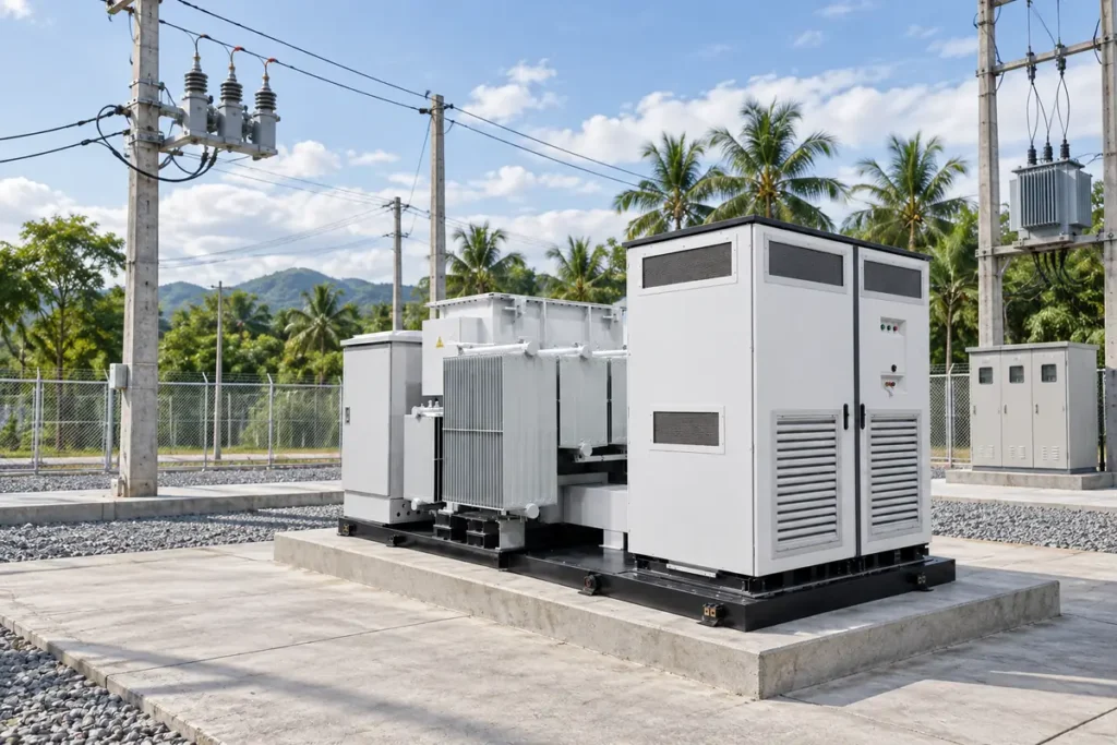
“European style” generally describes a compact, walk-in or non-walk-in arrangement in which the transformer and medium-voltage (MV) switchgear sit in separate, coordinated compartments. In a PV block, the inverter converts DC to low-voltage AC; the booster transformer raises voltage, commonly to 10, 12, 20 or 35 kV; the MV panel then connects the block to a collector circuit. Metering, surge protection, auxiliary supply, control wiring and an earth bar complete the package.
The distinction is functional rather than a universal product standard. IEC 62271-200 addresses AC metal-enclosed switchgear above 1 kV, including internal-arc classification and partitioning. IEC 62271-1 sets common requirements for high-voltage switchgear. The transformer is assessed under the relevant IEC 60076 parts, and the complete assembly still needs local utility approval, cable calculations and a site earthing design.
Efficiency comes from matching the electrical interfaces
Transformer and inverter operating point
Choose transformer rating from the inverter’s maximum apparent power, reactive-power range, clipping strategy and ambient derating. An illustrative 1,250 kVA transformer carrying 1,000 kVA at 0.8 power factor is at 80% of nameplate apparent load; copper loss is approximately 0.8², or 64%, of the declared full-load loss (assuming the same temperature and waveform). This is why guaranteed no-load and load losses must be stated separately at a declared reference temperature under IEC 60076-1.
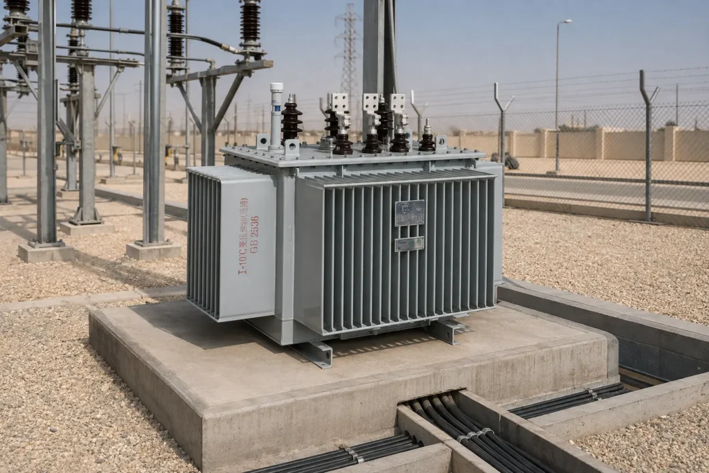
Three-dimensional wound-core transformers can reduce core mass and no-load loss compared with a conventional laminated design, but the project should accept only measured values from the agreed test plan. A three-dimensional wound-core transformer product page can help establish a baseline; it is not a substitute for project-specific loss guarantees or a witnessed test.
Protection, harmonics and cable drop
Inverter current is electronically controlled and can contain switching-frequency components. Request the inverter manufacturer’s harmonic spectrum, fault-current contribution and ride-through settings; then coordinate transformer impedance, MV relay curves and fuse selection. A simple voltage-drop check is Vdrop = I × Z. If a 1,000 kVA, 400 V bus carries about 1,443 A at unity power factor, even a 2 mΩ additional path represents roughly 2.9 V per phase and 4.2 kW of three-phase I²R loss. The exact result depends on conductor temperature and power factor, so treat this as an illustrative calculation.
For 35 kV PV collection, a combined transformer package such as the ZGS/ZG-35 photovoltaic combined transformer can be evaluated for its stated 500–1,600 kVA range, 35 kV rating and low-voltage options. Confirm short-circuit withstand, vector group, tap range and cable terminations against the utility data sheet.
Outdoor enclosure, thermal design and maintainability
PV sites combine dust, monsoon rain, salt mist, high solar gain and limited service access. IEC 60529 defines IP-code test methods; it does not by itself prove resistance to UV, corrosion or internal condensation. Specify the required IP level for each compartment, door gasket, pressure relief path, drain, anti-condensation heater and coating system. An IP54 or higher enclosure is often considered for exposed equipment, while the correct value depends on dust concentration, wash-down practice and the utility’s specification.
Separate heat sources in the layout. Transformer losses, inverter switching losses and sun-loaded roof surfaces can raise internal air temperature well above ambient. Ask for temperature-rise test data, fan duty, filter replacement interval and derating curves. The YB-12 intelligent integrated prefabricated substation layout illustrates independent high-voltage, transformer and low-voltage rooms, automatic ventilation options and a published normal-product enclosure grade of IP33D; an outdoor PV project may require a different enclosure specification.
Allow front and rear working clearances, lifting points, cable-bending radius and a safe isolation sequence. IEC 62271-200 internal-arc classification (when specified and tested) concerns personnel protection for defined installation conditions; it is not permission to omit barriers, remote operation or site arc-flash studies.
European versus American style: a project decision
| Dimension | European-style integrated box | American-style pad-mounted approach | Procurement implication |
|---|---|---|---|
| Compartment logic | Separate MV, transformer and LV/inverter sections; configurable protection | Transformer and switchgear commonly share a sealed pad-mounted tank | Check access, isolation and utility operating practice |
| Cooling and service | Airflow and doors can be designed by compartment | Sealed oil tank reduces exposed live parts but limits field access | Compare heat rejection, oil handling and outage procedures |
| Footprint | Compact, with cable routing and lifting frame planned as a package | Often compact at the pad, with different cable-entry geometry | Freeze foundation and trench drawings early |
| Protection flexibility | Ring-main unit, vacuum switch or fuse options can be coordinated | Integrated switching and transformer protection are commonly specified together | Match relay, fuse and inverter fault-current data |
| TCO tendency | Factory integration may reduce site wiring and commissioning hours | Sealed construction may reduce routine exposure but can increase replacement complexity | Model losses, spares, logistics, labour and downtime; avoid price-only claims |
Application and dimension matrix
| Application | Typical block size | Voltage / enclosure focus | Evidence to request |
|---|---|---|---|
| Utility PV string-inverter block | 630–1,600 kVA | 0.4–0.8 kV LV to 10–35 kV MV; dust and heat | Loss guarantees, thermal derating, IP and internal-arc options |
| Rooftop or C&I solar | 250–1,000 kVA | Compact footprint, noise and fire separation | IEC 60076-11 if dry type; room ventilation and acoustic data |
| Desert or coastal solar | 1,000–2,500 kVA | High UV, salt, sand and 45 °C-plus ambient | Corrosion system, filters, condensation control and altitude correction |
| Hybrid PV plus battery feeder | 630–2,000 kVA | Bidirectional power and frequent cycling | Overload cycle, harmonics, protection coordination and SCADA map |
Standards, tests and commercial compliance
Build the tender around a traceable evidence pack:
- IEC 62271-200: metal-enclosed MV switchgear, partitioning and optional internal-arc classification.
- IEC 62271-1: common switchgear requirements, ratings and test principles.
- IEC 60076-1: transformer general requirements, ratings and routine/type test framework.
- IEC 60076-11: dry-type transformer requirements, including environmental and fire behaviour classes.
- IEC 60529: IP-code test method for enclosures; pair it with UV and corrosion specifications.
- IEC 61850: communication and substation-automation models; define the edition, data objects and testing scope for SCADA integration.
Standards define requirements and methods, not an automatic “IEC-certified” label. Require routine test reports for each unit, agreed type or special tests, calibration traceability and a deviation list. Unsupported compliance wording can delay utility approval, customs release or grid energisation.
Procurement actions that prevent late redesign
- Issue one interface schedule covering inverter AC voltage, maximum kVA, reactive range, harmonics, MV voltage, frequency, vector group, impedance, tap range and earthing.
- Set site assumptions: ambient temperature, altitude, solar exposure, humidity, pollution, seismic class, IP requirement, noise limit and access restrictions.
- Request dimensional GA drawings, foundation loads, cable-entry details, lifting points, heat-rejection data and a maintenance/isolation sequence before purchase order.
- Capitalise losses using the owner’s tariff and duty cycle. For example, 1.2 kW no-load loss × 8,760 h = 10,512 kWh/year; add load-loss energy from the hourly profile and value downtime separately.
- Witness agreed routine tests and close the IEC 61850 signal list, protection settings and spare-parts list during factory acceptance—not after shipment.
Specify the interfaces as one system. Jubang can be included in a like-for-like enquiry when the buyer needs configurable transformer, switchgear and enclosure documentation. Verify every rating, test and environmental class against the project specification and the issued quotation.
Frequently asked questions
What is a European inverter boost integrated box substation?
It is a factory-coordinated package that combines an inverter, step-up transformer, MV switchgear, protection, metering and auxiliaries in separated compartments. The “European” description refers to the arrangement and operating philosophy; the applicable IEC and local utility requirements still govern the design.
How does an inverter booster integrated machine improve efficiency?
Shorter LV connections, matched transformer impedance and factory-tested interfaces can reduce resistive loss and commissioning rework. Efficiency gains must be demonstrated with declared inverter and transformer losses at the project load profile, not inferred from the word “integrated.”
What is the difference between a European and American style substation?
European-style packages usually separate MV, transformer and LV functions in a coordinated enclosure, while American-style pad-mounted units commonly use a sealed transformer tank with integrated switching. Utility operating practice, access rules, fault levels and local codes should decide the selection.
How do you reduce losses in a PV step-up substation?
Specify low no-load and load-loss values, keep LV cable runs short, select an appropriate impedance and operate near the transformer’s efficient load range. Validate harmonics, conductor temperature, ventilation energy and annual duty-cycle calculations before claiming savings.
What IP rating is suitable for an outdoor inverter booster?
Many exposed sites begin the discussion at IP54 or higher, but IEC 60529 only covers ingress testing. Confirm dust, rain, wash-down, salt, UV, condensation and maintenance conditions; the final rating may differ by compartment.
How do you select transformer capacity for a solar farm?
Start with maximum apparent power, reactive-power requirements, clipping, ambient/altitude derating and future expansion. Check the hourly load profile and harmonics, then select the next rating that meets temperature-rise and protection limits without creating excessive permanent no-load loss.
References
- International Electrotechnical Commission, IEC 62271-200.
- International Electrotechnical Commission, IEC 60076-1 and IEC 60076-11.
- International Electrotechnical Commission, IEC 60529.
- International Electrotechnical Commission, IEC 61850.
Losses are a design input, not a footnote. In PV collection, the highest efficiency is usually won before fabrication: align the interfaces, prove the losses and design for the climate that will actually operate the equipment. When your project reaches the quotation stage, review the complete specification with Jubang and request a documented, testable configuration.