From transformers and switchgear to ring main units, substations, circuit breakers and smart components, Jubang provides integrated product support for power distribution projects.
Discover Jubang’s strengths in technology R&D, quality testing and smart manufacturing, supporting reliable electrical equipment and efficient power distribution solutions for global customers.
From technical consultation and OEM/ODM customization to EPC support, smart O&M, delivery documentation and after-sales service, Jubang supports your project at every stage.
Explore Jubang Group’s development history, intelligent manufacturing base, R&D platforms, CNAS-accredited laboratory and global project service capabilities.
SCB Dry-Type Transformer Room Design: Clearances, Ventilation and Fire Strategy
Release Time: 2026-08-05
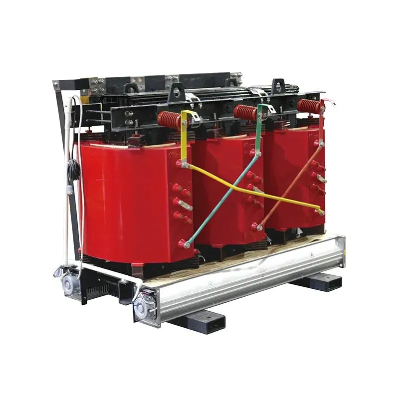
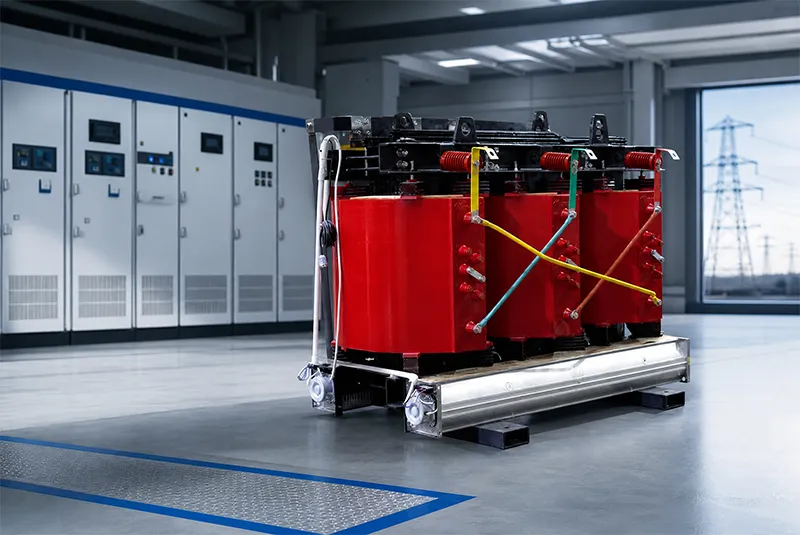
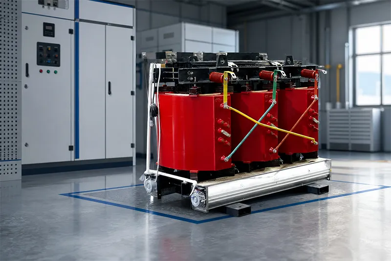
SCB dry type transformer room design starts from the offered unit’s outline drawing, declared enclosure type and the project’s fire and access rules — not from a generic kVA table or a copied clearance sketch. Coordinate the service envelope, fire behaviour class request, compartment interfaces and maintenance routes on approved drawings first; treat heat rejection and airflow as a linked but separate engineering package handled in the dry-type transformer ventilation guide.
Part 1. Why does SCB room design start with the OEM envelope?
An indoor SCB dry-type transformer room must fit the offered unit: its outline dimensions, terminal arrangement, cooling-air direction, enclosure category, lifting points and documented service envelope. The Siemens cast-resin planning guide and the ABB dry-type transformer design guide both treat manufacturer outline data as the basis for room layout, circulation and inspection access. Nameplate kVA alone does not define wall positions, door swings or fire interfaces.
Begin the multidisciplinary review once the electrical designer has frozen the one-line diagram, the proposed transformer configuration and the room’s place in the wider power transformer selection hub documentation set. Mechanical, fire, structural and procurement disciplines then work from the same drawing issue rather than from assumptions carried over from another project.
Part 2. Which clearances belong on coordinated drawings?
Clearances serve more than one purpose at once: cooling-air movement, terminal access, inspection, lifting, cable entry, panel door swing and safe working space around live parts. IEC 60076-11 treats several installation conditions, including restricted ventilation, as matters for agreement between purchaser and manufacturer rather than as values that can be copied from an unrelated project.
Important: Do not publish or procure against a generic clearance mm figure taken from another transformer, room or jurisdiction. Show the OEM service envelope on coordinated plans and sections, then let the project electrical rules, access standards and fire engineer review the result; source context: IEC 60076-11 special service and agreement clauses.
Clearance / envelope item
Drawing evidence required
Review question
Send with quote
Overall outline and lifting points
OEM outline drawing on plan/section
Is the handling route free from beams, ducts and switchgear?
Yes
Cooling-air approach and departure zones
Outline plus airflow direction arrow
Do walls, doors or cable trenches block the declared path?
Yes
HV/LV terminal and cable-entry space
Terminal arrangement detail
Can cables terminate without violating the service envelope?
Yes
Control-panel and monitor access
Panel elevation and door swing
Can operators reach interfaces without removing room finishes?
Yes
Inspection and cleaning access
Maintenance side identification
Can routine tasks be done without dismantling unrelated equipment?
Yes
Fire-compartment boundary distance
Fire strategy drawing
Does the layout respect the agreed compartment line and egress?
Yes
The table is a coordination register, not a spacing code. The transformer OEM, electrical designer and fire engineer remain the decision owners.
Part 3. How does enclosure type change the room boundary?
IEC 60076-11 distinguishes non-enclosed, enclosed and totally enclosed dry-type transformer arrangements. The category changes how room air reaches the active cooling surfaces and how much of the thermal path sits inside the equipment boundary. The SGB-SMIT cast-resin planning guide similarly treats enclosure protection and airflow as a single review item for installation planning.
Enclosure category (IEC terminology)
Room-design consequence
Typical coordination note
Non-enclosed
Room surfaces and openings form much of the cooling boundary
Wall/louver positions must match OEM airflow direction
Enclosed
Equipment shell modifies the air path; room still provides intake/exhaust
Do not assume the room can shrink because an enclosure exists
Totally enclosed
Heat rejection path depends on the offered cooling arrangement
Confirm whether remote heat exchanger, ducted or other means are in scope
An enclosure can address contamination or touch protection while creating a ventilation constraint. That is why enclosure selection belongs in the same room-design workshop as clearance and access, not in a late procurement addendum.
Part 4. What do F0 and F1 mean for dry-type transformers?
Fire behaviour class is part of the purchase specification vocabulary for dry-type transformers in IEC 60076-11. F0 and F1 describe defined fire-behaviour categories used when the purchaser and manufacturer agree that fire performance is part of the requirement. The standard introduces the classes; it does not make every dry-type transformer in every room automatically F0 or F1 without an agreed specification and a manufacturer statement for the offered design.
Use the classes as RFQ language:
Request the class when the project fire strategy or purchaser specification calls for it.
Require the OEM to state, in writing, which class applies to the offered configuration and which test or declaration supports that statement.
Do not infer F0 or F1 for a JUBANG product family from this article or from generic resin-insulated marketing language alone.
Fire class describes transformer fire behaviour under the standard’s definitions. It does not, by itself, replace the building fire engineer’s work on compartmentation, detection, suppression, egress or local code routes.
Part 5. Where does fire strategy meet the transformer room?
Fire strategy reaches the transformer room through boundaries, penetrations, cable routes, detection, shutdown logic and emergency access — not only through the transformer body. The Siemens planning guide specifically flags coordination where ventilation ducts cross fire-rated construction. That is an interface item for the fire engineer and the responsible authority, not a detail the HVAC designer resolves alone.
Fire and ventilation interfaces to list on the review
Fire-compartment lines on room plans and sections
Door ratings, self-closing requirements and egress paths
Duct, louver and damper penetrations with their control narrative
Cable-tray and busduct routes that cross rated boundaries
Detection, alarm and shutdown signals affecting HVAC or fans
Maintenance access that must remain usable after fire measures are installed
Heat rejection, loss schedules, fan duty and the complete airflow path belong in the dedicated dry-type transformer ventilation guide. This article stops at the interface: the room layout must leave space and penetrations that the ventilation design can use without contradicting the fire strategy.
Part 6. What maintenance access must the room preserve?
Room design fails operationally when a technically acceptable layout cannot be serviced. The ABB guide links layout to routine inspection; the Siemens guide expects maintenance and handling clearances to remain available after installation. Treat access as an operational requirement with the same status as electrical clearance.
Maintenance task
Access input to show on drawings
Common layout failure
Visual inspection of windings and connections
Unobstructed viewing sides
Switchgear placed in the inspection line
Terminal tightening and cable work
Working space at HV/LV terminals
Cable trenches that block hand access
Lifting or rolling for major work
Path from delivery door to pad
Narrow doors or turns not checked against outline
Filter or screen cleaning (if applicable)
Reach to intake screens or panels
Architectural louvers without service clearance
Monitor, sensor or fan service
Panel door swing and stand-off
Panel mounted flush to a wall with no working space
Agree which tasks will be performed with the unit energized versus isolated, and reflect that in the room access plan and the site operating procedure. The room drawing should make the chosen approach credible.
Part 7. SCB dry-type transformer room design RFQ checklist
Room-design intentions bind only when they are written into the RFQ and returned on the OEM drawing set.
RFQ item
Why the supplier and designer need it
Send with quote
Transformer configuration and quantity
Fixes the outline basis
Yes
OEM outline drawing with service envelope
Controls clearances and lifting
Yes
Enclosure category and options
Links equipment boundary to room
Yes
Requested F0/F1 class, if applicable
Makes fire behaviour an explicit requirement
Yes
Room plan, sections and door schedule
Shows walls, openings and routes
Yes
Fire-compartment strategy and penetration list
Coordinates rated boundaries
Yes
Cable-entry locations and trench routes
Prevents terminal-space conflicts
Yes
Maintenance and inspection access requirements
Preserves operability
Yes
Site conditions from IEC special-service list
Triggers OEM review of environment
Yes
Ventilation responsibility statement
Separates room layout from airflow design
Yes
Interface responsibilities (OEM / EPC / fire / HVAC)
Avoids silent gaps
Yes
Required documentation set and deviations
Makes the offer reviewable
Yes
If mechanical ventilation is in scope, attach or reference the loss-led ventilation input package described in the sibling ventilation article so the supplier and HVAC designer share one duty case.
Part 8. Which JUBANG equipment fits after the room package is defined?
Once the outline drawing, enclosure request, fire-class language, access plan and interface list exist, a resin-insulated dry-type configuration can be discussed against project documents. The JUBANG 35 kV resin-insulated dry-type transformer page is a product-family starting point for that conversation. It is not a pre-approved answer for every room, fire class or clearance envelope.
Fit Boundary
A good fit: EPC and owner teams that hold coordinated room drawings, an enclosure requirement, a fire-strategy interface list and a documented F0/F1 request where the project needs it.
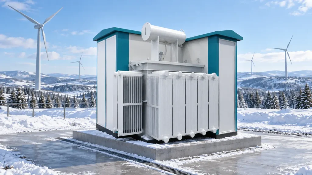
Not the right path: projects that only need airflow or loss-led ventilation sizing without a layout package yet — start with the ventilation sibling article; projects specifying oil-immersed equipment or a prefabricated substation boundary without the same room-design inputs.
Confirm first: the offered configuration, enclosure type, OEM outline clearances, any fire-behaviour class statement in the supplier documentation, and the drawing issue referenced in the quotation.
This page assigns no universal clearance value, F0/F1 class, fire rating or compliance outcome to any JUBANG product. Those values come from the offered design, the approved drawings and the project’s engineering authorities.
Next step:send the approved room drawing package — outline drawing, room plans, enclosure and fire-class request, site conditions and required document list — for a project-specific configuration review.
FAQ
What clearances does an SCB dry-type transformer room need?
The clearances needed are those shown on the OEM outline drawing for the offered configuration, plus the project’s electrical, access and fire rules. There is no single mm table that applies to every SCB room; coordinate the documented service envelope instead of copying another project.
What is the difference between F0 and F1 fire behaviour class?
Both are fire-behaviour categories defined in IEC 60076-11 for dry-type transformers when the purchaser and manufacturer agree that fire performance is part of the requirement. The exact meaning is standard-defined; confirm which class applies to the offered unit in the supplier documentation.
How does enclosure type affect room design?
Non-enclosed, enclosed and totally enclosed categories change how room air and equipment boundaries interact. Enclosure choice can help with contamination or touch protection while altering the ventilation path, so it must be fixed before final room dimensions are issued.
What should coordinated transformer room drawings show?
At minimum: the OEM outline and service envelope, terminal and cable-entry zones, cooling-air direction, lifting and maintenance paths, door swings, fire-compartment lines and major penetrations. Ventilation calculations and fan duties belong in the separate ventilation input package.
How does fire strategy affect a dry-type transformer room?
Through compartment boundaries, rated doors, penetrations for ducts and cables, detection and shutdown interfaces and egress — coordinated with the fire engineer. Transformer fire class is one input; it does not replace the building fire design.
What maintenance access should be planned?
Plan credible access for inspection, terminal work, cleaning of intake components if used, panel service and any agreed lifting or rolling path for major maintenance. Show these routes on the room drawings before construction fixes walls and equipment positions.
What data belongs in an RFQ for room design?
Outline drawing, enclosure type, F0/F1 request if applicable, room plans and sections, fire-interface list, cable routes, site conditions, maintenance requirements, interface responsibilities and the documentation set expected in the offer.
Where is ventilation handled relative to room layout?
Room layout and clearances are owned in this specification path. Loss schedules, airflow paths, fan duty and the ventilation RFQ register are owned in the dry-type transformer ventilation guide. Link both packages on multidisciplinary drawings.
Products are exported to more than 100 countries and regions such as Africa, the Middle East, and the United Kingdom and Europe. It is a leading manufacturer of power distribution equipment in China.

 JUBANG