From transformers and switchgear to ring main units, substations, circuit breakers and smart components, Jubang provides integrated product support for power distribution projects.
Discover Jubang’s strengths in technology R&D, quality testing and smart manufacturing, supporting reliable electrical equipment and efficient power distribution solutions for global customers.
From technical consultation and OEM/ODM customization to EPC support, smart O&M, delivery documentation and after-sales service, Jubang supports your project at every stage.
Explore Jubang Group’s development history, intelligent manufacturing base, R&D platforms, CNAS-accredited laboratory and global project service capabilities.
OLTC vs Off-Circuit Tap Changer: Choosing a Voltage Regulation Approach
Release Time: 2026-07-15
OLTC vs off-circuit tap changer is first an operating-duty decision. An OLTC changes transformer taps while the unit remains energized and carrying load; an off-circuit tap changer, also called a de-energized tap changer (DETC), may be operated only after the transformer is de-energized. The right choice depends on whether voltage adjustment must occur during normal service or can be scheduled in an outage.
Neither device should be chosen from a generic tap range, step size, or maintenance interval. The transformer winding design, actual system-voltage duty, control philosophy, site access, liquid/design arrangement, and approved project documents decide the offered configuration.
Part 1. What separates OLTC from an off-circuit tap changer?
The physical difference is straightforward, but the procurement implication is substantial. IEEE C57.131 covers on-load and de-energized tap-changers and their motor-drive mechanisms. In service terms, the OLTC supports a tap change without first taking the transformer out of service, while the DETC/off-circuit design requires de-energized operation.
That distinction should not be reduced to “advanced” versus “simple.” A project may deliberately use a de-energized device when the network can tolerate a planned adjustment outage. Conversely, a stable installation may still need an OLTC if its approved operating duty requires voltage correction while load remains connected.
Selection question
OLTC
Off-circuit tap changer / DETC
When is the tap position changed?
During energized, load-carrying service when the offered design and controls are specified for that duty
Only after the transformer is de-energized
What does the selection start with?
The need to regulate voltage without a planned interruption
The ability to schedule an outage before adjustment
What must the RFQ define?
Regulation duty, control/drive interfaces, winding data, tap data, lifecycle access, and documentation
Winding data, required adjustment positions, outage procedure, and documentation
What should not be assumed?
A generic tap scheme, common liquid layout, common maintenance interval, or automatic standard compliance
That a manual or off-circuit adjustment can respond to live voltage variation
Important: Treat the outage strategy as an engineering input, not as a procurement afterthought. The applicable device must be selected with the transformer winding and system duty, not substituted after the design is released. Source context: IEC/IEEE 60214-2.
Part 2. Which voltage-regulation duty calls for each approach?
Start with the operating scenario. If the transformer must move between tap positions while energized to support an approved voltage-regulation duty, an OLTC is the relevant category to evaluate. If the required adjustment is infrequent and can be made under a controlled outage, an off-circuit tap changer may be the more appropriate category.
The system study and the responsible engineering authority need to define the duty. Useful inputs include the source-voltage variation to be addressed, downstream voltage needs, load behavior, parallel-transformer operating rules, permitted interruptions, and the interface between transformer control and the wider network. Those inputs decide whether an energized change is necessary; they do not arise from a catalogue label alone.
Project condition
Direction for evaluation
Decision owner
Voltage adjustment must be available while the transformer remains in service
Evaluate an OLTC and its specified drive/control interfaces
Responsible system or project engineer
Adjustment may be made only during planned maintenance or a controlled outage
Evaluate a DETC/off-circuit design and the safe isolation procedure
Owner and responsible operating authority
The requirement is unclear or conflicts with the operation plan
Hold the device selection until the duty and authority are documented
Project technical authority
For a practical application framework, IEC/IEEE 60214-2 is intended to assist selection of tap-changers used with tapped transformer or reactor windings. It is a selection reference, not evidence that any particular offered transformer is suitable for a project.
Part 3. Why must tap range and step data stay project-specific?
Tap range and step data belong to the transformer and system design package. They are not safe generic values to copy between projects, even where the transformers appear similar. The required adjustment band, individual positions, winding arrangement, voltage study, control behavior, and any parallel-operation constraints must be reconciled by the responsible design team and OEM.
Ask for the offered tap data in a traceable format rather than asking a supplier to “include an OLTC” or “provide taps.” The request should identify the nominal and operating voltage conditions, the required voltage-regulation duty, whether changing while energized is required, the intended position reference, and any constraints imposed by connected equipment or controls.
Information that should travel together
Transformer rating, vector group, impedance basis where applicable, winding voltages, and neutral arrangement.
Nominal system voltage plus the documented operating-voltage conditions that create the regulation duty.
Required tap range and individual step data as supplied or approved by the project/OEM, not copied from a generic guide.
Required tap-position indication, local/remote interface, alarms, interlocking, and integration expectations where an OLTC is being evaluated.
Parallel-transformer, protection, and operating constraints that affect allowable tap-position management.
The CIGRE work on OLTC best practices notes that manufacturer specification sheets are based on required application information and can differ for special duties. That is why missing duty data should trigger a clarification, not a guessed tap arrangement.
Part 4. What happens inside an OLTC during a tap change?
An OLTC is more than a tap-position label. In common designs, a tap selector chooses the next winding connection and a diverter switch transfers current between positions through a controlled switching sequence. A motor-drive mechanism supplies and sequences the mechanical action. The precise arrangement depends on the offered design, so terminology should be confirmed against the OEM documentation.
IEC 60214-1 applies to resistor- and reactor-type on-load tap-changers, de-energized tap-changers, and motor drives. It covers performance requirements and test methods; it does not make a generic device configuration or project compliance claim.
The diverter function matters because load transfer can involve switching energy. The tap selector matters because it establishes the selected winding connection. The motor drive matters because its control, interlocks, position feedback, and mechanical behavior need to match the project’s operating concept. These are specification and lifecycle questions, not just construction details.
Tip: In a technical review, request the offered tap-changer arrangement, drive documentation, and terminal/control interface information together. Separating them can hide a mismatch between transformer winding duty and the intended operating method. Source context: IEC 60214-1.
Part 5. What do liquid, maintenance, and condition-monitoring boundaries mean?
Lifecycle scope differs materially between an OLTC and an off-circuit device because energized switching introduces additional components and duty. CIGRE’s transformer-maintenance guide includes both on-load and de-energized tap changers, OLTC tests, liquid and paper tests, dissolved gas analysis, maintenance inspection, and sensing/monitoring in its maintenance framework.
For typical arcing-switch OLTC designs, the diverter or selector area may use a tap-changer liquid compartment separated from the main transformer liquid. The peer-reviewed OLTC monitoring review explains the rationale: arcing can degrade liquid and generate particulate or gaseous by-products. This is a design boundary, not a universal rule. Verify whether the offered OLTC has a separate compartment, what liquid applies, how sampling is handled, and which OEM instructions govern service.
Condition assessment may combine inspection, liquid-condition review, dissolved-gas analysis where applicable, dynamic resistance measurement (DRM), vibro-acoustic measurement, temperature or motor-drive information, and trend review. None of these methods should be quoted as a universal maintenance interval or pass/fail limit. The relevant OEM manual, design, operating history, liquid system, risk plan, and responsible authority determine the programme.
Lifecycle topic
OLTC question to put in the project file
DETC/off-circuit question to put in the project file
Access
How will the drive and tap-changer assembly be safely accessed and isolated?
How will the transformer be safely de-energized and positioned before an adjustment?
Liquid/design boundary
Is there a dedicated tap-changer liquid volume, and what procedure applies to it?
What insulating medium and inspection procedure apply to the offered design?
Monitoring
Which methods are relevant to the offered arrangement and maintenance strategy?
Which inspection and position-verification records are required after an adjustment?
Evidence
Which OEM maintenance documents, test records, and exception routes are required?
Which isolation, position, and return-to-service records are required?
Part 6. How should standards and documentation be used in a specification?
Standards should organize the request, not become an unsupported compliance statement. IEC 60214-1 addresses performance requirements and test methods for both on-load and de-energized tap-changers and motor drives. IEEE C57.131-2024 similarly covers electrical and mechanical performance/test requirements. IEC/IEEE 60214-2 provides application guidance for selection.
In an RFQ, name the applicable standard edition only when the contract or technical authority requires it. Then request the offered device documentation, declared tests, drawings, instructions, and exceptions. Do not state that a transformer “meets” a standard merely because the standard is named in an article or a bid request.
The broader transformer sequence also matters. For installation, site checks, and energization planning beyond tap-changer selection, see JUBANG’s related transformer installation and pre-energization guide. The final commissioning decision remains with the project’s responsible authority and approved documents.
Important: A standard reference does not replace the project specification, OEM manual, or approved drawing. Request a documented response to each required item and record any deviation before the purchase decision. Source context: IEEE C57.131-2024.
Part 7. What should an OLTC or DETC RFQ include?
An RFQ should describe the voltage-regulation duty before it requests a device. That keeps the commercial comparison aligned with transformer design and operating responsibility.
RFQ input list
Transformer rating, winding voltages, vector group, impedance basis where applicable, neutral arrangement, cooling arrangement, and site/application context.
Nominal and documented operating voltage conditions, load profile, parallel-operation requirements, and the engineering reason for voltage adjustment.
A clear statement of whether tap changes must occur while energized and carrying load, or whether planned de-energized adjustment is acceptable.
Required tap range and individual step data as approved project/OEM inputs; no generic range or step assumption.
Requested OLTC, DETC, or supplier-proposed arrangement only after the duty is defined, plus the required diverter-switch, tap-selector, and motor-drive documentation where relevant.
Control, position indication, interlocking, alarm, local/remote, and monitoring interface requirements.
Insulating-liquid/design arrangement, sampling or inspection expectations, maintenance access, outage strategy, and condition-monitoring expectations.
Applicable contract documents and standards, required drawings, test/document package, factory/site acceptance responsibilities, and exception approval route.
This list does not choose a device or approve a tap scheme. The responsible engineer, owner, OEM, and contract documents must decide whether an OLTC, a de-energized tap changer, or another design approach fits the actual transformer and network duty.
Part 8. When is a JUBANG transformer enquiry a fit?
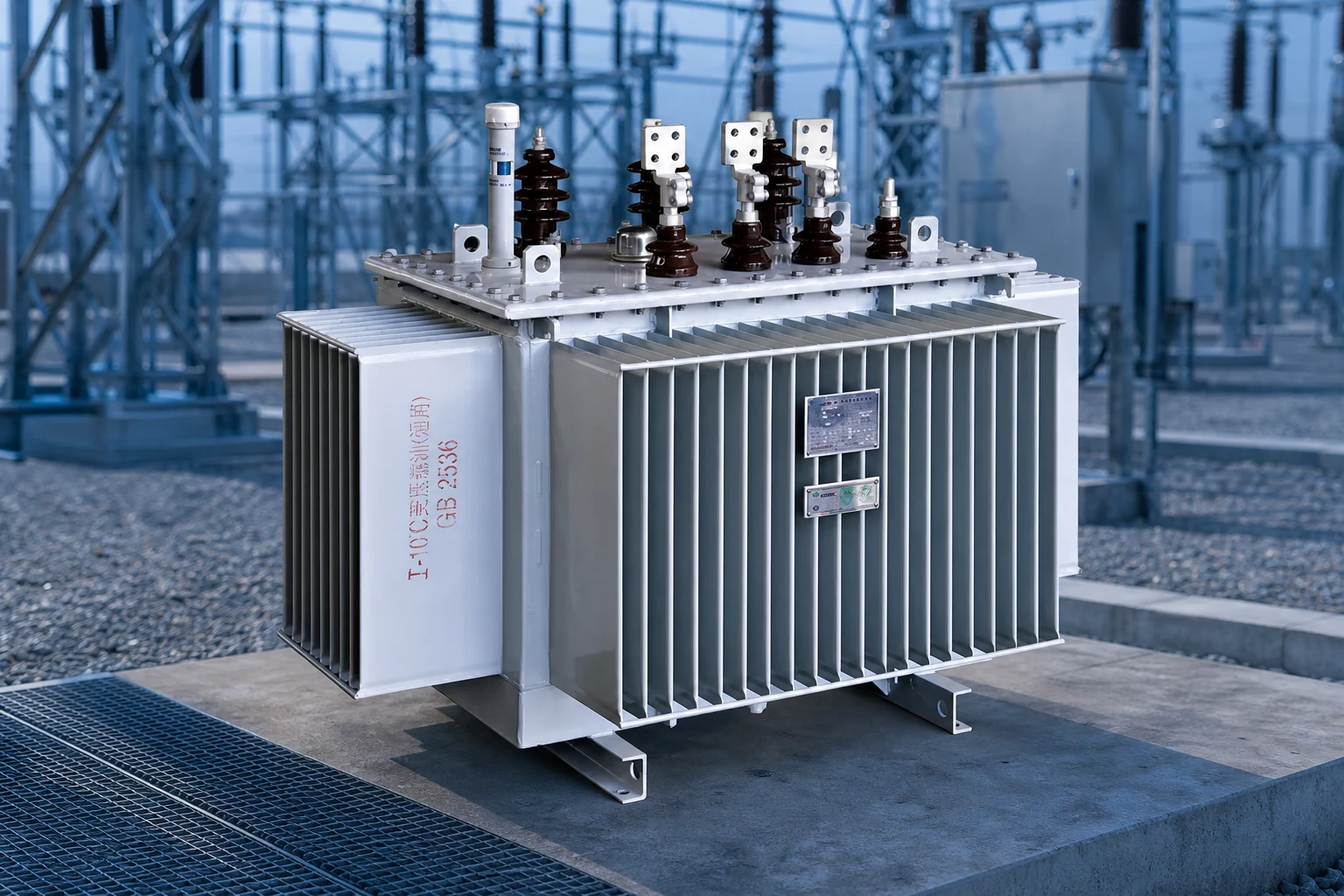
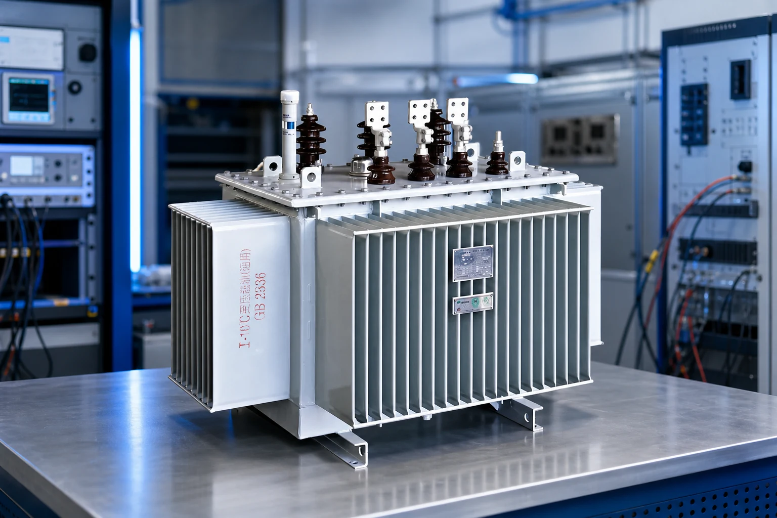
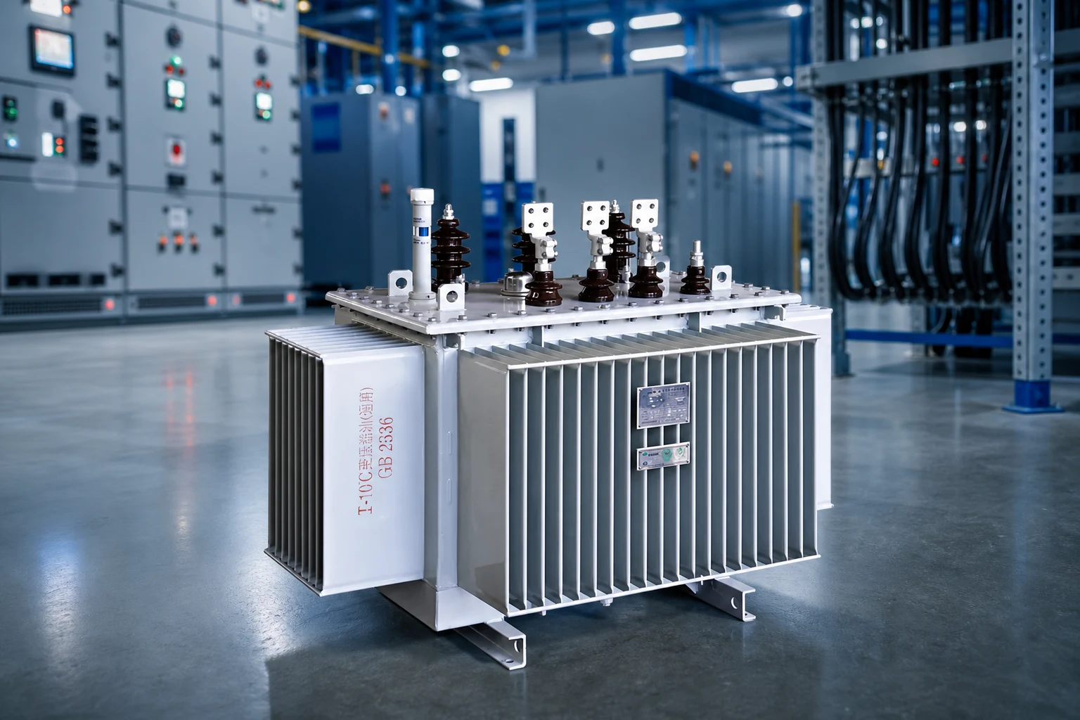
A JUBANG enquiry is relevant when the buyer already has, or is ready to develop, a project-specific voltage-regulation duty and transformer specification. JUBANG publicly presents 6–10 kV oil-immersed power transformers and 35 kV oil-immersed power transformers. Use those pages as a starting point for equipment context, then submit the RFQ inputs so the offered configuration and documents can be discussed.
Fit Boundary
This article does not establish that any JUBANG transformer includes an OLTC, a DETC, a particular tap range or step arrangement, a dedicated tap-changer liquid compartment, a monitoring system, or compliance with a named standard. Confirm the offered tap-changer design, applicable documents, test scope, maintenance responsibilities, and project acceptance path in writing.
Next step: submit an OEM/ODM transformer consultation with the voltage-regulation duty, outage strategy, winding/tap inputs, control requirements, standards, and documentation needs. That allows the project team to compare a suitable configuration without treating a generic comparison as an engineering release.
FAQ
What is the main difference between an OLTC and an off-circuit tap changer?
An OLTC changes taps while the transformer is energized and carrying load. An off-circuit tap changer, or DETC, is operated only after the transformer is de-energized. The practical selection question is whether voltage adjustment must be available during service.
Can an off-circuit tap changer regulate voltage under load?
No. Its operating boundary is de-energized adjustment. If the approved duty requires voltage correction while load remains connected, evaluate an OLTC with the required winding, drive, and control interfaces.
When should a project consider an OLTC?
Consider an OLTC when the documented system and operating duty requires tap changes without a planned interruption. Confirm the required regulation behavior, transformer winding data, control concept, maintenance access, and acceptance documentation before selecting an offered arrangement.
Does every transformer need an OLTC?
No. A transformer that can be adjusted during a planned outage may be better served by a de-energized tap changer. The decision follows the approved voltage-regulation duty and operating strategy, not a default product category.
What are the diverter switch and tap selector?
In common OLTC arrangements, the tap selector chooses the next winding connection and the diverter switch transfers load current through a controlled switching sequence. Exact architecture varies by offered design, so use the OEM documentation for the project-specific arrangement.
Do OLTCs need separate insulating liquid?
Not every design should be described the same way. Typical arcing-switch arrangements may segregate tap-changer liquid because switching can affect liquid condition. Confirm the offered compartment arrangement, applicable liquid, sampling approach, and maintenance instructions with the OEM.
How should tap range and step data be specified?
Provide the project/OEM-approved range and individual step data with winding information, operating-voltage conditions, control duty, and parallel-operation constraints. Do not copy generic values from another transformer or article.
Which standards are relevant to OLTC and DETC selection?
IEC 60214-1, IEEE C57.131-2024, and IEC/IEEE 60214-2 are relevant performance, test, and application references. Their use in a project must be confirmed by the contract and responsible technical authority.
Products are exported to more than 100 countries and regions such as Africa, the Middle East, and the United Kingdom and Europe. It is a leading manufacturer of power distribution equipment in China.

 JUBANG