FZ (R)N25-12D-T Series indoor high-voltage AC compressed air load switch fuse combination device
• It is currently the most advanced medium voltage vacuum load switch...
From transformers and switchgear to ring main units, substations, circuit breakers and smart components, Jubang provides integrated product support for power distribution projects.
Discover Jubang’s strengths in technology R&D, quality testing and smart manufacturing, supporting reliable electrical equipment and efficient power distribution solutions for global customers.
From technical consultation and OEM/ODM customization to EPC support, smart O&M, delivery documentation and after-sales service, Jubang supports your project at every stage.
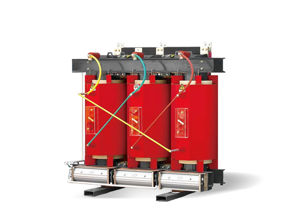
ZGS□ Combined transformer (Commonly known as American box transformer), its structure is “品” type, transformer and high and low voltage equipment are closely connected as one, among them, three sides of the transformer exposed to the air, good heat dissipation conditions, and can be separated from high and low voltage equipment enclosure, easy maintenance.
The transformer adopts chip type oil tank, no oil pillow, fully enclosed S□series oil immersed transformer, high and low voltage bushing, tap switch, oil level indicator, pressure release valve, oil release valve and so on are installed on the high voltage chamber body end plate, reasonable position, easy to obsere and operate. High voltage room, low voltage room between the steel plate separated, high voltage room, low voltage room transformer is relatively independent, and maintain a complete box to change the whole, compact structure, small volume, light weight. The power distribution switchgear is installed on the high and low voltage side.
Small size, compact structure, easy installation;
Can be used for ring network, also can be used for terminal, reliable protection of personal safety;
Low damage, low noise and superior performance;
Low temperature rise, strong load capacity.
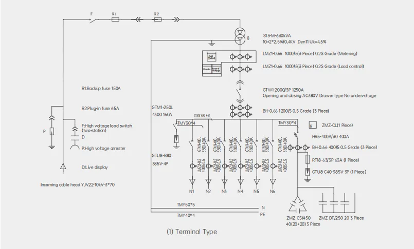
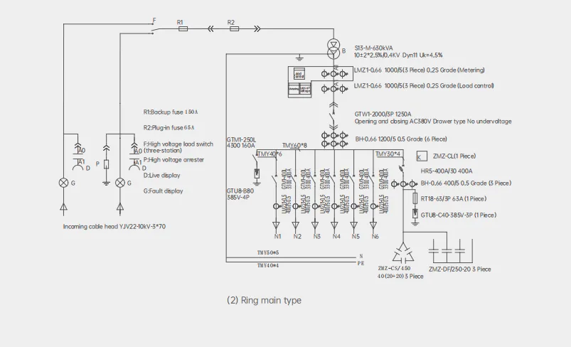
High voltage interval
The high voltage interval contains high pressure line Incoming sleeve, load switch operating handle, non-excited pressure regulating tap switch, plug-in fuse, pressure release valve, oil temperature gauge, oil level gauge, pressure gauge, oil filling hole, oil discharge valve, etc.
Low voltage interval
In the low voltage distribution cabinet, an intelligent undervoltage controller is installed, which has the function of identifying the abnormal voltage of the substation low voltage bus. When the high-voltage one or two-phase fuse is blown and the substation low-voltage measurement voltage is abnormal, the controller sends out an action signal to make the circuit breaker trip. When the three-phase voltage of the low voltage side is lower than 50% of the normal voltage, the controller does not send an action signal, so as to avoid the trip of 10kV high voltage line or power failure maintenance caused by all the low voltage switch trip. Can be installed according to user requirements with telemetry, remote communication function of comprehensive power distribution tester.
Cooling condition: Air self-cooling;
Altitude: ≤1000m;
Environment temperature: The outdoor environment temperature is not higher than 40℃ and not lower than-45℃: the monthly average temperature is not higher than 30℃ and the annual average temperature is not higher than 20℃;
Relative humidity: At 25℃, the relative humidity of the air does not exceed 95%, and the average monthly temperature does not exceed 90%;
Shockproof level: Horizontal acceleration is not greater than 0.3m/s², verical acceleration is not large 0.15m/ s²;
Surrounding environment: Installation environment should be free from obvious pollution, explosive, corrosive gas and dust;
Installation site: There should be no violent vibration and impact, and it is required to be installed on a cement platform or other smooth and solid platform;
When the above conditions cannot meet the use requirements, the user shall negotiate with the manufacturer.
Box variable performance parameters
| Rated
capacity kV.A |
Voltage
combination kV |
Connection group | Loss kW | No-load
current % |
Short circuit
impedance % |
Weight kg | Overall dimensions mm
L(Length)×W(Width)×H(Height) |
Gauge
Vertical / Horizontal |
||||
| High
voltage |
Low
voltage |
No-
load |
Load 75℃ | Body
weight |
Oil
weight |
Total
weight |
||||||
| 30 | 10.5 10 6.3 6 |
0.4 | Dyn11 Yzn11 Yyn0 |
0.08 | 0.63/0.6 | 1.5 |
4.0 |
185 | 70 | 310 | 790×660×925 | 550/400 |
| 50 | 0.1 | 0.91/0.87 | 1.3 | 255 | 85 | 395 | 820×675×1030 | 550/400 | ||||
| 63 | 0.11 | 1.09/1.04 | 1.2 | 280 | 95 | 430 | 845×690×1065 | 550/400 | ||||
| 80 | 0.13 | 1.31/1.25 | 1.2 | 320 | 100 | 480 | 865×715×1075 | 550/550 | ||||
| 100 | 0.15 | 1.58/1.5 | 1.1 | 380 | 110 | 540 | 880×720×1120 | 550/550 | ||||
| 125 | 0.17 | 1.89/1.8 | 1.1 | 444 | 115 | 600 | 910×750×1110 | 550/550 | ||||
| 160 | 0.2 | 2.31/2.2 | 1.0 | 510 | 130 | 690 | 910×750×1200 | 550/550 | ||||
| 200 | 0.24 | 2.73/2.6 | 1.0 | 610 | 150 | 840 | 1220×745×1220 | 550/550 | ||||
| 250 | 0.29 | 3.2/3.05 | 0.90 | 720 | 190 | 950 | 1240×775×1300 | 660/660 | ||||
| 315 | 0.34 | 3.83/3.65 | 0.90 | 835 | 200 | 1065 | 1230×750×1345 | 660/660 | ||||
| 400 | 0.41 | 4.52/4.3 | 0.80 | 1010 | 240 | 1255 | 1330×825×1375 | 660/660 | ||||
| 500 | 0.48 | 5.41/5.15 | 0.80 | 1170 | 260 | 1485 | 1455×915×1390 | 660/660 | ||||
| 630 | Dyn11 Yyn0 |
0.57 | 6.2 | 0.60 |
4.5 |
1375 | 320 | 1800 | 1540×920×1510 | 660/660 | ||
| 800 | 0.7 | 7.5 | 0.60 | 1620 | 365 | 2120 | 1650×1035×1555 | 820/820 | ||||
| 1000 | 0.83 | 10.3 | 0.60 | 1780 | 405 | 2450 | 1855×1235×1600 | 820/820 | ||||
| 1250 | 0.97 | 12.0 | 0.50 | 2065 | 560 | 2855 | 1925×1285×1680 | 820/820 | ||||
| 1600 | 1.17 | 14.5 | 0.50 | 2470 | 650 | 3400 | 2025×1355×1730 | 820/820 | ||||
| 2000 | 1.55 | 18.3 | 0.40 | 5.0 | 2700 | 695 | 4460 | 2190×1900×1950 | 820/820 | |||
| 2500 | 1.83 | 21.2 | 0.40 | 3230 | 870 | 5330 | 2240×1940×1980 | 1070/1070 | ||||
Note: ① The load loss values above the middle slash apply to the Dyn11 or Yzn11 connection group, and the load loss values below the slash apply to the Yyn0 connection group.
② The overall dimension is only for reference in the selection. The final size is subject to the product outline drawing.
| Rated capacity
of transformer (kVA) |
Low voltage side (0.4kV)
Rated current (A) |
High voltage
side(10kV) Rated current (A) |
Plug-in fuse
capacity (A) |
Backup fuse capacity
(A) |
Low voltage
configuration main switch capacity (A) |
| 50 | 72.2 | 2.89 | 4 or 6 | 10 | 100 |
| 80 | 115.5 | 4.62 | 10 | 20 | 160 |
| 100 | 144.3 | 5.77 | 10 | 20 | 200 |
| 125 | 180.4 | 7.22 | 10 | 25 | 250 |
| 160 | 230.9 | 9.24 | 15 | 40 | 315 |
| 200 | 288.7 | 11.55 | 20 | 40 | 400 |
| 250 | 360.8 | 14.43 | 25 | 50 | 500 |
| 315 | 454.7 | 48.19 | 31.5 | 80 | 630 |
| 400 | 577.4 | 23.09 | 40 | 80 | 800 |
| 500 | 721.7 | 28.87 | 50 | 100 | 1000 |
| 630 | 909.3 | 36.37 | 65 | 125 | 1250 |
| 800 | 1154.7 | 46.19 | 80 | 125 | 1600 |
| 1000 | 1443.4 | 57.74 | 100 | 200 | 2000 |
| 1250 | 1804.2 | 72.17 | 125 | 250 | 2500 |
| 1600 | 2309.4 | 92.38 | 160 | 320 | 3200 |
| Rated current (A) | Rated
voltage (kV) |
Impulse withstand Voltage
(kV) |
Power
frequency withstand voltage (Imin.kV) |
Rated short- time withstand
current(kA/s) |
Number of load operations | Number of machine operations |
| 315 | 12 | 75 | 42 | 20/s | 100 | 2000 |
| 630 | 12 | 75 | 42 | 20/s | 100 | 2000 |