From transformers and switchgear to ring main units, substations, circuit breakers and smart components, Jubang provides integrated product support for power distribution projects.
Discover Jubang’s strengths in technology R&D, quality testing and smart manufacturing, supporting reliable electrical equipment and efficient power distribution solutions for global customers.
From technical consultation and OEM/ODM customization to EPC support, smart O&M, delivery documentation and after-sales service, Jubang supports your project at every stage.
Explore Jubang Group’s development history, intelligent manufacturing base, R&D platforms, CNAS-accredited laboratory and global project service capabilities.
Air Circuit Breaker: Operating Principle, Main Parts and Ratings
Release Time: 2026-11-08
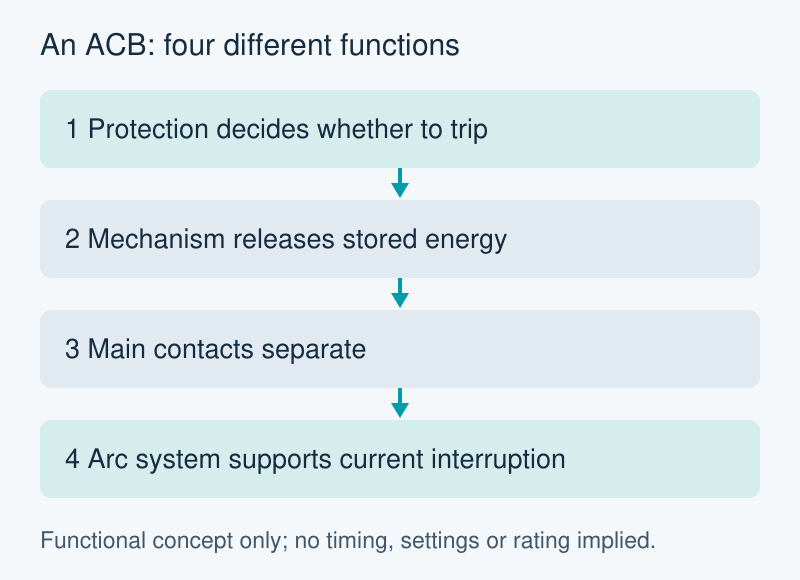
An air circuit breaker (ACB) is a switching and protection device that uses air as part of its arc-interruption system. In low-voltage distribution, understanding it means separating three events: the protection system decides to trip, the mechanism opens the contacts, and the arc system enables current interruption within the breaker’s specified duty.
Those events explain why a large current number on a catalogue page is not enough to describe an ACB. The trip-unit functions, mechanical configuration and fault-duty ratings each answer a different engineering question.
How an air circuit breaker interrupts current
During normal closed operation, the main contacts provide the current path. A protection function responds when its configured operating conditions are met. It initiates a release of the operating mechanism, which separates the contacts. Opening contacts under current can produce an arc; contact separation alone does not fully explain interruption.
The arc-interruption system manages that arc. In a typical LV ACB, the arc chute uses a plate arrangement to divide and cool it, helping the device interrupt current. “Air” here does not mean that every ACB uses an external compressed-air supply. Nor does the name establish a particular voltage range, breaking capacity or operating time.
Functional explanation only. The blocks do not specify a time delay, trip setting, exact internal arrangement or tested breaking capacity.
This distinction matters when reading a product description. An electronic trip unit can provide several protection functions, but its menu does not replace the breaker’s interruption rating. Equally, an arc-chute illustration says nothing by itself about whether the offered protection functions match the project requirements.
Main parts: connect the component to its function
The trip unit is the protection decision element. Its available functions depend on the selected controller and accessories. The operating mechanism supplies the mechanical action needed to open or close the contacts. The main contacts conduct current when closed; the arc chute serves a different role during interruption.
The operator panel also contains information about mechanical state. An open/closed indicator concerns contact position. A spring-charge indication concerns stored energy in the mechanism. On a withdrawable version, a separate position indication concerns the breaker relative to its cradle or guide frame. These are different observations, even when the windows sit close together.
Reading one indication as though it answered all three questions is a mistake. A charged mechanism does not mean that the main contacts are closed. An open indication does not establish the complete isolation and verification conditions needed for work. The exact manufacturer’s manual defines the indicators, interlocks and permitted operations for the selected device.
Read the ratings as different duties
A rating must stay attached to its conditions. In particular, the same breaker family can have different declared breaking duties at different operating voltages. Comparing two offers requires the same voltage and the same kind of duty, rather than whichever catalogue number is largest.
Field
What it describes
What to keep with it
Ue
Rated operational voltage
The system voltage and the duties declared at that voltage
Rated current / frame designation
Current capability or frame identification, as defined by the manufacturer
The exact device configuration and applicable operating conditions; do not treat frame size as a protection setting
Icu
Rated ultimate short-circuit breaking capacity
Declared voltage and applicable test conditions
Ics
Rated service short-circuit breaking capacity
The separately declared service duty; do not assume it equals Icu
Icw
Rated short-time withstand current
The specified duration and conditions; it describes carrying a duty, not the same duty as interrupting it
The table is a reading guide, not a selection calculation. It does not establish an installation’s available fault current or required protection coordination. Those inputs come from the project studies and equipment specification. A value without its voltage or time condition can create a misleading comparison even when both catalogue entries are correct.
Fixed and withdrawable versions need different documents
A fixed version and a withdrawable version describe different mounting arrangements. A withdrawable assembly adds a relationship between the breaker and its cradle or guide frame, together with the associated position and interlock information. That does not make every drawer, cradle or accessory interchangeable.
The useful documentation question is therefore specific: which breaker, mounting assembly, controller and accessories form the offered configuration? Its manual and arrangement information should correspond to that configuration. A generic family brochure cannot resolve every terminal, control-power or mechanical-interface detail.
The published JUBANG GTW1 air circuit breaker information distinguishes fixed/drawer versions and provides ordering choices for poles, current, voltage and controller. Those fields give an enquiry a practical structure. Identify the required configuration and request the matching rating table, protection-function description, dimensions and interface documentation.
This keeps the final discussion connected to evidence: what the device is required to carry, what it must interrupt, which protection functions are offered and how the selected assembly connects to the rest of the switchgear.
Products are exported to more than 100 countries and regions such as Africa, the Middle East, and the United Kingdom and Europe. It is a leading manufacturer of power distribution equipment in China.

 JUBANG