From transformers and switchgear to ring main units, substations, circuit breakers and smart components, Jubang provides integrated product support for power distribution projects.
Discover Jubang’s strengths in technology R&D, quality testing and smart manufacturing, supporting reliable electrical equipment and efficient power distribution solutions for global customers.
From technical consultation and OEM/ODM customization to EPC support, smart O&M, delivery documentation and after-sales service, Jubang supports your project at every stage.
Explore Jubang Group’s development history, intelligent manufacturing base, R&D platforms, CNAS-accredited laboratory and global project service capabilities.
DIN Rail Types and Dimensions: A Guide for Electrical Control Panels
Release Time: 2026-11-07
DIN rail is a shaped mounting rail used to support compatible electrical and control components inside a cabinet. The useful specification is more than a nominal width: the profile, depth and component mounting arrangement must work together.
A component described as “DIN-rail mounted” still needs a declared mounting interface. Before planning a panel layout, identify the rail profile from its drawing and compare it with the component’s mounting information. Similar-looking metal sections are not enough to establish a match.
DIN rail profiles: identify the family first
Top-hat, miniature top-hat, C-section and G-section names describe different mounting-profile families. The cross-section is the useful starting point because it shows the geometry that the component’s mounting arrangement must engage.
Profile family
Useful identifying information
What still needs checking
Top-hat / TS35
Nominal 35 mm width; common examples have different depths
The exact profile and the device’s declared mounting arrangement
Miniature top-hat / TS15
A smaller family described with nominal 15 mm width
The component data for that smaller interface
C-section
A distinct section family identified by its drawing
The specified profile and any required mounting arrangement
G-section
A distinct profile with an asymmetric cross-section
The actual drawing, device interface and intended orientation
The family name narrows the question; it does not complete the compatibility check. Where a drawing or device sheet names a specific rail arrangement, retain that information in the component schedule rather than replacing it with the broader phrase “standard DIN rail.”
Width and depth are different dimensions
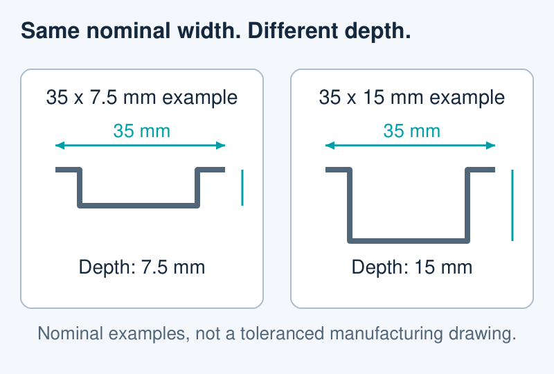
Two top-hat rail examples can share a nominal 35 mm width while having different depths. The cited manufacturer examples list 35 mm width with 7.5 mm depth and 35 mm width with 15 mm depth. The numbers describe the referenced profiles, not every rail or every device that might be mounted on them.
Width identifies one aspect of the mounting geometry. Depth describes another aspect of the section. Neither number, on its own, establishes the finished component position or the complete cabinet arrangement.
Nominal dimensional examples from the cited manufacturer data. The illustration explains width versus depth; it does not provide manufacturing tolerances or confirm a component’s fit.
The complete manufacturer drawing remains the reference for the selected rail. Additional dimensions, material and mounting details should come from that drawing and the applicable product data, not from a simplified explanatory cross-section.
Mounting slots do not define the device interface
Slotted and non-slotted versions are another distinction to record. The mounting-hole information and the rail cross-section describe different features. A familiar slot pattern therefore does not establish that the rail presents the required component interface.
The selected examples show this separation in their dimensional data: profile dimensions and mounting-hole dimensions are listed independently. Keeping both fields in the drawing review avoids using a photograph of the perforations as a substitute for checking the section.
The rail’s primary role here is mechanical support. Its presence does not, by itself, establish an approved electrical function or bonding arrangement. Any such role needs its own verified design information.
Four checks for a control-panel layout
1. Identify the profile. Record the rail family and selected drawing. Compare the actual section with the component’s declared mounting information. This resolves what is intended to fit, without assuming that a common width guarantees compatibility.
2. Keep the mounting details separate. Record the rail’s fixing arrangement and the relevant component mounting details as distinct inputs. This makes an adapter or other specified mounting provision visible in the component schedule instead of leaving it as an assumption.
3. Check the component envelope. The rail is only one part of the installed geometry. The device drawing describes the component around that interface. Compare the offered combination with the intended cabinet layout, including the access and connection information supplied for the device.
4. Close the cabinet-level review. The panel designer should review the complete layout and the applicable component conditions. A rail drawing alone cannot approve clearances, support duties or the finished assembly. Where information is missing, the drawing query should identify that missing condition explicitly.
These checks create a short information chain: selected rail drawing, component mounting data, component envelope and cabinet arrangement. A change at one point should be reviewed against the others rather than treated as an isolated substitution.
What to send with an OEM cabinet enquiry
JUBANG’s published OEM/ODM support includes low-voltage cabinet layout and component configuration. A useful layout enquiry should therefore identify the intended component family, its mounting documentation and the rail profile being considered.
Include the component schedule and available arrangement drawing, then mark any interface that still requires confirmation. That gives the cabinet team a defined mounting question to review. It also separates a request for a complete component layout from an unsupported assumption about a particular rail or clip.
The next decision is whether the documented component-to-rail arrangement fits the proposed cabinet design. It should be answered from the selected drawings and component data, not from the rail width alone.
Products are exported to more than 100 countries and regions such as Africa, the Middle East, and the United Kingdom and Europe. It is a leading manufacturer of power distribution equipment in China.

 JUBANG