From transformers and switchgear to ring main units, substations, circuit breakers and smart components, Jubang provides integrated product support for power distribution projects.
Discover Jubang’s strengths in technology R&D, quality testing and smart manufacturing, supporting reliable electrical equipment and efficient power distribution solutions for global customers.
From technical consultation and OEM/ODM customization to EPC support, smart O&M, delivery documentation and after-sales service, Jubang supports your project at every stage.
Explore Jubang Group’s development history, intelligent manufacturing base, R&D platforms, CNAS-accredited laboratory and global project service capabilities.
Power Transformer: Working Principle, Main Parts and Types
Release Time: 2026-11-07
A power transformer transfers electrical energy between windings through a changing magnetic field. Its winding arrangement establishes the voltage relationship. The core, insulation and cooling construction turn that magnetic principle into equipment that can perform a specified electrical duty.
The operating principle and the physical construction answer different questions. A turns-ratio equation explains an ideal voltage relationship. It does not establish the transformer’s capacity, operating conditions or suitability for a particular project.
Power transformer working principle
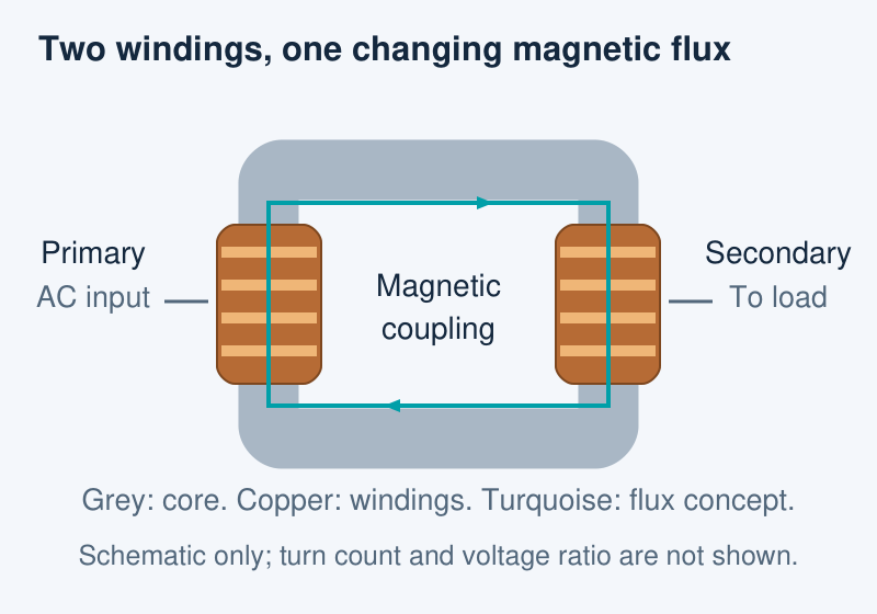
In a conventional two-winding transformer, an alternating supply produces changing magnetic flux. That flux links the primary and secondary windings and induces voltage. The core provides the shared magnetic path; the windings form the electrical input and output circuits.
The drawing below separates those roles. It illustrates magnetic coupling rather than a physical terminal layout, turn count or complete three-phase connection arrangement.
Conceptual two-winding arrangement. The flux path represents the coupling principle, not a calculated field distribution. Winding turns and voltage ratio are not represented by the graphic.
What the turns ratio explains
For an ideal two-winding model, the voltage ratio follows the winding turns ratio: V2/V1 = N2/N1. Here, the voltages refer to the corresponding windings, and N represents their numbers of turns.
The ideal model neglects losses. Increasing voltage does not create additional power; the ideal current relationship changes in the opposite direction. Real equipment requires additional rating and operating information. In three-phase equipment, winding connections must also be understood before interpreting line-voltage relationships.
Main parts and the information each one carries
A component map helps connect a transformer drawing with the information needed to understand it. The map below describes functions; it is not a promise that every model contains an identical set of accessories.
Part or arrangement
Main question
Useful document information
Magnetic core
What construction provides the magnetic path?
Core arrangement and construction description
Primary and secondary windings
How are the electrical circuits arranged?
Winding ratings and connection diagram
Insulation system
How are the energized parts separated?
Declared insulation arrangement and relevant rating information
Cooling arrangement
How is heat managed in the offered configuration?
Cooling description and specified operating conditions
Tank or enclosure and connections
How does the equipment interface with its surroundings?
General arrangement and connection details
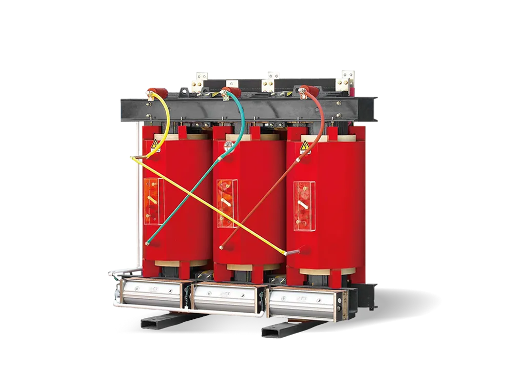
This reading order avoids treating a visible exterior as the whole transformer. A tank photograph can identify a construction family without showing the winding connection. A coil photograph can show resin construction without establishing the complete equipment rating.
The offered configuration should therefore remain consistent across the general arrangement, winding information and operating-condition documents. A difference between them is a question to resolve, rather than a detail to infer from appearance.
Oil-immersed and dry-type describe construction
Liquid-immersed and dry-type transformers use different insulation and cooling arrangements. In a dry-type transformer, the magnetic circuit and windings are not immersed in an insulating liquid. Cast-resin construction is one dry-type approach; the term does not describe every possible dry-type design.
These examples show why construction information belongs beside the electrical ratings. The type name alone does not establish a universal efficiency, overload capability, operating environment or preferred application. Those conclusions need the actual model data and project conditions.
Keep voltage, construction and application labels separate
A transformer description can contain several labels at once. “Step-down” describes a voltage relationship. “Oil-immersed” or “cast-resin” describes construction. A reference to a distribution project describes the intended system role. These labels are useful, but they do not replace one another.
When interpreting a product description, connect each label to its supporting information. Voltage transformation belongs with winding ratings and connections. Construction belongs with insulation and cooling details. Application suitability belongs with the declared equipment duty and the project requirements.
Read the equipment in three layers
Electrical layer: identify the input and output ratings and the connection information. This establishes what voltage relationship the offered equipment is intended to provide. It also shows where a simplified two-winding concept needs more detailed three-phase documentation.
Construction layer: locate the core and windings in the design description, then identify the insulation and cooling arrangement. This explains how the physical equipment implements the electrical function. It also prevents a tank, coil or enclosure illustration from being mistaken for a complete specification.
Project-interface layer: compare the connection and general-arrangement information with the intended installation interfaces and stated operating conditions. The objective is to identify the documents needed for the next review, not to derive a final equipment selection from a principle diagram.
With those layers separated, a reader can move from “how does it work?” to the relevant product information without confusing a magnetic relationship, a construction type and an approved project configuration.
Products are exported to more than 100 countries and regions such as Africa, the Middle East, and the United Kingdom and Europe. It is a leading manufacturer of power distribution equipment in China.

 JUBANG