From transformers and switchgear to ring main units, substations, circuit breakers and smart components, Jubang provides integrated product support for power distribution projects.
Discover Jubang’s strengths in technology R&D, quality testing and smart manufacturing, supporting reliable electrical equipment and efficient power distribution solutions for global customers.
From technical consultation and OEM/ODM customization to EPC support, smart O&M, delivery documentation and after-sales service, Jubang supports your project at every stage.
Explore Jubang Group’s development history, intelligent manufacturing base, R&D platforms, CNAS-accredited laboratory and global project service capabilities.
PV Booster Station Design Inputs: Inverter, Transformer and MV Interface Data
Release Time: 2026-07-14
PV booster station design inputs should be issued as one controlled interface package, not collected as isolated catalogue fields. Before an EPC team asks a supplier to configure a station, it should freeze the inverter operating data, the transformer duty and insulation inputs, and the MV collection/PCC constraints that connect them.
This guide is a cross-vendor handoff checklist for preliminary design and RFQ preparation. It does not select a universal vector group, grounding scheme, transformer impedance, kVA margin, or grid-code solution; those choices belong to the approved project design and the selected equipment documentation.
Part 1. What is a usable PV booster station design-input package?
A usable package lets every party work from the same electrical boundary. It identifies the inverter output at the LV side, the transformer and station scope in the middle, and the MV collection/PCC conditions at the other side.
Interface
Minimum decision data
Typical owner
Inverter to transformer
Model, AC voltage, rated output, current, count, operating envelope, harmonic/control information
Inverter vendor / EPC
Transformer and station
Voltage ratio, duty basis, insulation and cooling conditions, accessory and document requirements
The package should also record the drawing revision, calculation owner, governing documents and open assumptions. NREL’s PV-plant electrical-design study treats the plant as an interconnected system rather than a collection of standalone components; the same discipline is useful when the booster station is being specified.
Important: A product name, a nominal power value and a destination country do not form an engineering input package. Issue the one-line diagram and the current revision of the project assumptions with every RFQ. (NREL 64227)
Part 2. Which inverter data must be frozen before transformer design starts?
The inverter documentation is the starting point because its AC interface defines conditions the transformer and station must accommodate. SMA’s Sunny Central transformer requirements, for example, call for matching LV winding voltage to inverter AC output, considering temperature-dependent inverter power, and accounting for the full system grounding context. Those are model-specific examples of a broader handoff requirement.
Ask the inverter supplier or EPC to provide:
exact inverter make, model, firmware/control version where relevant, and quantity per transformer block;
nominal and permitted AC voltage at the electrical connection point, frequency and rated current;
rated active power and the expected P/Q operating envelope, including any continuous reactive-power duty requested by the project;
harmonic spectrum, line-to-line and line-to-ground voltage information, dV/dt, filter, switching and transformer-interface requirements stated by that inverter manufacturer;
maximum operating and ambient-temperature conditions used for the inverter duty calculation;
fault contribution, protective functions and any permitted switching/energization sequence;
written confirmation of any approved transformer winding, insulation, shielding, tap or impedance conditions for that specific model.
Do not infer these fields from an inverter family name. SMA’s Sunny Highpower technical information shows why: its connection and impedance limits vary by named model, and its calculation considers the full path to the PCC rather than only the transformer.
IEEE C57.159, harmonic, and LCL-filter context
IEEE C57.159 is an application guide for transformers used in distributed PV systems, not a universal transformer rating or project acceptance specification. It calls attention to inverter–transformer interaction, possible resonance, and the need for the inverter supplier to specify harmonic content for transformer design. Request the manufacturer’s waveform and harmonic information rather than inserting a generic THD limit in the RFQ.
Where the inverter design includes an LCL filter, include the approved filter topology, component data or equivalent model, damping/control approach, switching-frequency information, and the study boundary to the transformer and PCC. LCL filters can have a resonance that requires damping, while transformer inductance can be part of the grid-connection frequency response; a PV converter damping review and experimental transformer/filter research describe this context. Do not treat a generic LCL value, damping method, or resonance frequency as portable between inverter models or networks.
Part 3. Which transformer inputs must be specified rather than assumed?
The transformer supplier needs a duty specification, not an instruction to copy a previous renewable project. The RFQ should state what must be designed, tested and documented, while leaving equipment-specific engineering to the selected supplier and project authority.
A universal vector group, grounding type or impedance
Mechanical/site
Layout, transport limits, corrosion/pollution conditions, maintenance access
Standard dimensions or outdoor enclosure details
Verification
Required drawings, routine/type-test evidence, FAT points, manuals and as-built documents
That a catalogue test applies to the quoted configuration
SMA’s Sunny Central requirements explicitly connect transformer thermal design to the inverter load curve, ambient conditions and reactive-power loading. That supports asking for the operating profile early; it does not support publishing a fixed margin for every PV project.
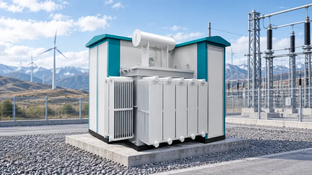
JUBANG’s published ZGS Combined Transformer is relevant as an integrated-product context after the approved inputs are known. Its product-page configurations and connection groups are examples in that product’s own scope, not a PV booster-station prescription.
Split-winding and dual-secondary LV topology
If a block uses a three-winding transformer with two LV secondary windings, or another split-winding/dual-secondary arrangement, identify each inverter-to-secondary assignment separately. State the winding nominal voltages and ratings, phasor and grounding requirements, inverter switching relationship, cable data, protection zones, and the calculation cases that include one or both inverter groups. IEEE C57.159 specifically notes that separate dedicated inverters on two LV windings can require a resonance evaluation when their switching is not synchronized. This is a prompt for an inverter-vendor and transformer-supplier study, not a recommendation to select that topology for every PV block.
K-factor and nonsinusoidal-load review
A K-factor label is not a substitute for the actual inverter harmonic spectrum and transformer thermal design. IEEE C57.110-2018 provides methods and application information for transformers supplying a portion of nonsinusoidal load current, but its stated scope is two-winding transformers and excludes rectifier transformers. For a PV booster transformer, provide the spectrum, loading profile, cooling conditions, and relevant inverter/filter study outputs so the supplier can decide whether a harmonic-loss evaluation, a stated K-factor, or another documented design approach applies. Do not impose a K-factor or derating value without that project-specific analysis.
Part 4. How should inverter, transformer and collection-system interfaces be reconciled?
Treat the AC path from each inverter to the PCC as one coordinated path. The selected transformer is only one part of the voltage-drop, impedance, protection and control picture; cables, collection feeders, upstream transformers and grid strength can also matter.
Reconciliation step
Deliverable
Review question
1. Freeze boundaries
Latest single-line diagram and block count
Where does each supplier’s responsibility start and end?
2. Normalize bases
Voltage, MVA/kVA and impedance bases; frequency; study revision
Are all values on compatible bases?
3. Assemble path data
Inverter interface requirements, transformer data, cable/feeder parameters, PCC data
Has any series element been omitted?
4. Review operating cases
Maximum export, low generation, reactive-power operation, temperature/site cases
Which case governs which component?
5. Close actions
Assumption log, calculation owner, supplier deviations and approval route
Who accepts the final design choice?
The Sunny Highpower technical information uses total impedance between inverter and PCC as a model-specific design check and includes grid and series-transformer terms in its example calculation. Use that as a reminder to obtain a project study, not as a licence to reuse its allowable percentage for other inverter brands.
Part 5. Why do reactive-power duty and thermal conditions change the input package?
During reactive-power operation, current and voltage conditions can change, so the request belongs in the equipment input package rather than a late-stage control note. The IEA PVPS review documents that reactive-power frameworks and DER capabilities differ between jurisdictions, and that coordination is a central issue.
For each operating case, state:
active-power and reactive-power setpoint ranges, including duration and dispatch authority;
voltage-control mode or plant-controller interface, if defined;
whether the case is required by a utility/DSO/TSO document, a plant controller, or an owner target;
ambient temperature, solar loading, ventilation and other thermal boundary conditions;
whether nighttime or storage-coupled operation changes the cooling/duty pattern;
the calculation and approval party for losses, current, temperature and protection coordination.
Important: Do not state that a station complies with a grid code until the applicable local code, interconnection agreement, inverter settings and project studies have been reviewed together. (IEA PVPS Task 14)
Part 6. What must the MV interface and PCC package contain?
The MV interface is a multi-party boundary. The owner or EPC may know the physical route and commercial schedule; the utility controls or confirms certain PCC information; equipment suppliers need the approved design basis to configure their portion.
MV/PCC item
Input needed
Typical confirmation source
Collection system
Nominal voltage, feeder count, cable routes/lengths and available electrical parameters
EPC design package
Grid connection
PCC voltage, available fault level, utility study data and operating limits
Utility / DSO / TSO
Grounding and protection
Study basis, protection zones, coordination responsibilities and interlocks
Protection engineer / utility
Metering and communications
Revenue/plant metering boundary, SCADA signals, protocols and cybersecurity interface
Owner / EPC / utility
Site interface
Civil layout, access, environmental conditions, emergency and maintenance requirements
Owner / EPC
Compliance
Applicable country, utility and project documents; acceptance witnesses
Contract and design authority
The IEA PVPS report is useful context because it distinguishes regulatory frameworks and coordination practices rather than presenting one global rule. This is why an RFQ should name the governing documents and unresolved items instead of asserting “grid-code compliant” from a generic specification.
Part 7. How should an RFQ be issued, and which JUBANG product line may fit?
Issue one version-controlled RFQ with the data below attached or referenced. Invite suppliers to identify deviations, missing inputs and items that require a formal study instead of silently filling gaps with catalogue defaults.
RFQ input list
project location, one-line diagram, owner/EPC contact and document revision;
inverter make/model, number per block, AC output data and manufacturer interface requirements;
required P/Q operating cases and plant-controller/utility instructions;
MV collection and PCC data, including the available fault-study and cable/feeder information;
ambient, altitude, pollution/corrosion, layout, transport and maintenance constraints;
quotation scope boundary, delivery terms, target schedule and deviation register.
Where the approved one-line diagram and project conditions support a compact combined arrangement, review the JUBANG ZGS Combined Transformer with the JUBANG engineering team. The page is a product-line starting point, not a substitute for inverter compatibility confirmation, MV studies or utility approval.
Send the inverter datasheet, one-line diagram, preliminary MV/PCC data and site conditions through JUBANG Contact Us for a configuration review.
FAQs
What is the first document to send with a PV booster station RFQ?
Send the latest one-line diagram together with the inverter model and block count. It establishes the electrical boundaries that a model number alone cannot show.
Does the inverter manufacturer choose the transformer vector group?
Not universally. The inverter manufacturer’s model-specific documentation, the overall grounding and protection study, and the grid-side requirements must be reconciled by the approved design authority.
Can a transformer impedance value be copied from another solar project?
No. The relevant path includes inverter requirements, transformer data, cables, collection system and PCC/grid conditions. Confirm the project study basis before accepting a value.
Why must reactive-power operation be included in the input package?
Reactive-power requests can change operating current, voltage-control coordination and thermal duty. State the required P/Q cases and who governs them.
Is a published product page proof of grid-code compliance?
No. A product page can introduce a product line, but compliance depends on the local grid rules, interconnection agreement, selected configuration, tests and project approval.
What should be compared between booster-station quotations?
Compare the same controlled input revision: electrical interfaces, operating cases, scope boundary, tests, documents, accessories, exclusions and deviations—not price alone.
Products are exported to more than 100 countries and regions such as Africa, the Middle East, and the United Kingdom and Europe. It is a leading manufacturer of power distribution equipment in China.

 JUBANG