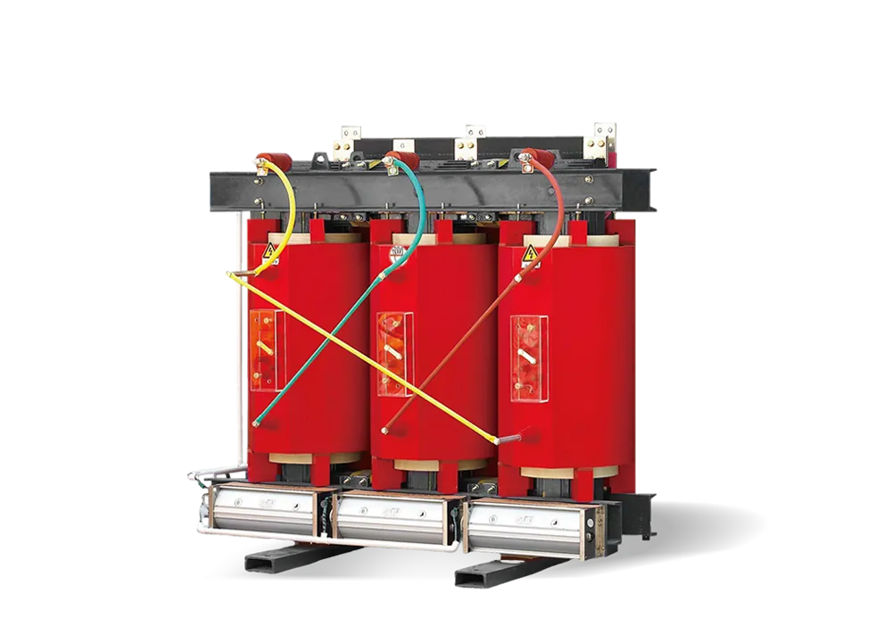
6-10kV SCB Resin-Insulated Dry-Type Transformer
Optimized Magnetic Circuit Energy Saving & Reduced Loss Low Noise Strong Overload...
From transformers and switchgear to ring main units, substations, circuit breakers and smart components, Jubang provides integrated product support for power distribution projects.
Discover Jubang’s strengths in technology R&D, quality testing and smart manufacturing, supporting reliable electrical equipment and efficient power distribution solutions for global customers.

From technical consultation and OEM/ODM customization to EPC support, smart O&M, delivery documentation and after-sales service, Jubang supports your project at every stage.

Explore Jubang Group’s development history, intelligent manufacturing base, R&D platforms, CNAS-accredited laboratory and global project service capabilities.


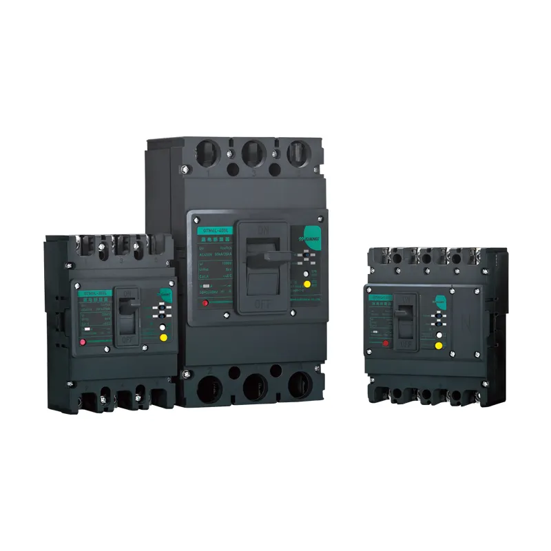
Compact structure
Undervoltage protection
Short circuit protection
Overload protection
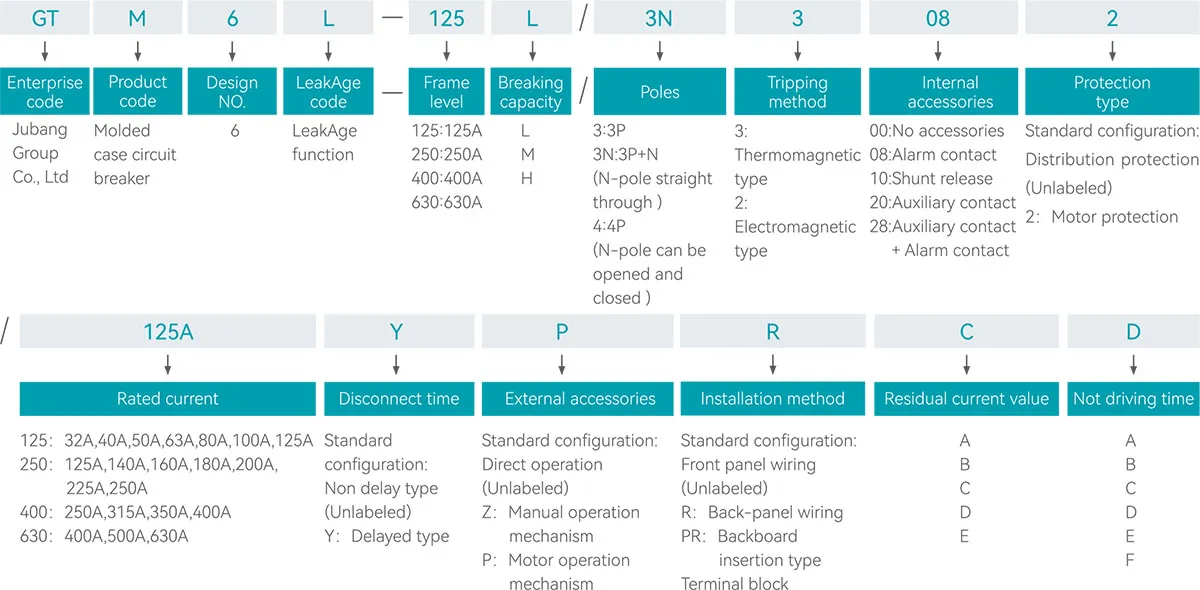
Notes:
Residual current action value GTM6L-125/250 default :C: GTM6L-400/630 default:D
A:50、100、200 B:100、200、300 C:200、300、500 D:300、500、1000 E:100、400、800
Extreme non driving time GTM6L-125/250 default :C; GTM6L-400/630 default:D
A:0.06、0.1、0.2 B:0.1、0.3、0.6 C:0.1、0.3、0.5 D:0.1、0.5、1 E:0.2、0.4、0.8 F:0.1、0.4、0.7
Capable of providing overload, short circuit, and undervoltage protection for equipment;
The indication and adjustment of leakAge parameters can be carried out on the circuit breaker panel;
The rated residual operating current and maximum breaking time can be adjusted according to the actual situation;
The current ranges from 32A to 630A
| Model | Frame level | Rated current(A) | |||||||||||||||||
| 32 | 40 | 50 | 63 | 80 | 100 | 125 | 140 | 160 | 180 | 200 | 225 | 250 | 315 | 350 | 400 | 500 | 630 | ||
| GTM6L-125 | 125 | ■ | ■ | ■ | ■ | ■ | ■ | ■ | |||||||||||
| GTM6L-250 | 250 | ■ | ■ | ■ | ■ | ■ | ■ | ■ | |||||||||||
| GTM6L-400 | 400 | ■ | ■ | ■ | ■ | ||||||||||||||
| GTM6L-630 | 630 | ■ | ■ | ■ | |||||||||||||||
| Model | GTM6L-125 | GTM6L-250 | GTM6L-400 | GTM6L-630 | ||||||||||||||||||||||
| GB/T14048.2 IEC60947-2 |
||||||||||||||||||||||||||
| Frame level | Inm(A) | 125 | 250 | 400 | 630 | |||||||||||||||||||||
| Operating Frequency | (Hz) | 50 | 50 | 50 | 50 | |||||||||||||||||||||
| Breaking Type | L | M | H | L | M | H | L | M | H | L | M | H | ||||||||||||||
| Poles | 3P | 3P+N,4P | 3P | 3P+N,4P | 3P | 3P+N,4P | 3P | 3P+N,4P | 3P | 3P+N,4P | 3P | 3P+N,4P | 3P | 3P+N,4P | 3P | 3P+N,4P | 3P | 3P+N,4P | 3P | 3P+N,4P | 3P | 3P+N,4P | 3P | 3P+N,4P | ||
| Rated Current | In(A) | 32,40,50,63,80,100,125 | 125,140,160,180,200,225,250 | 250,315,350,400 | 400,500,630 | |||||||||||||||||||||
| Rated Insulation Voltage | Ui(V) | 1000 | 1000 | 1000 | 1000 | |||||||||||||||||||||
| Rated Impulse Withstand Voltage | Uimp(kV) | 8 | 8 | 8 | 8 | |||||||||||||||||||||
| Rated working voltage | Ue(V) | AC 400 | AC 400 | AC 400 | AC 400 | |||||||||||||||||||||
| Arcing distance | (mm) | ≯50 | ≯80 | ≯100 | ≯100 | |||||||||||||||||||||
| Rated limit short-circuit breaking capacity | Icu(kA) | 25 | 35 | 50 | 25 | 35 | 50 | 35 | 50 | 70 | 50 | 70 | 100 | |||||||||||||
| Rated operating short-circuit breaking capacity | Ics(kA) | 12.5 | 25 | 35 | 12.5 | 25 | 35 | 25 | 35 | 50 | 35 | 50 | 70 | |||||||||||||
| Rated short- circuit making capacity | Icm(mA) | 25%Icu | 25%Icu | 25%Icu | 25%Icu | |||||||||||||||||||||
| Rated residual operating current | I△n(mA) | 30(Only non delay type) 200,300,500(Delayed type) |
30(Only non delay type) 200,300,500(Delayed type) |
300,500,1000 | 300,500,1000 | |||||||||||||||||||||
| Extreme non driving time/delayed type | (s) | 0.1,0.3,0.5 | 0.1,0.3,0.5 | 0.1,0.5,1 | 0.1,0.5,1 | |||||||||||||||||||||
| Rated residual non-operating current | I△no(mA) | I△no=I△n/2 | I△no=I△n/2 | I△no=I△n/2 | I△no=I△n/2 | |||||||||||||||||||||
| Usage category | A | A | A | A | ||||||||||||||||||||||
| Service Life | Mechanical Life(Times) | Maintenance free | 10000 | 10000 | 10000 | 10000 | ||||||||||||||||||||
| With maintenance | 20000 | 20000 | 20000 | 20000 | ||||||||||||||||||||||
| Electrical life(Times) | 4000 | 4000 | 2000 | 2000 | ||||||||||||||||||||||
| Overall dimensions (mm) | 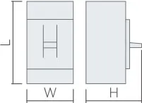 |
Width(W) | 92 | 122 | 92 | 122 | 92 | 122 | 107 | 142 | 107 | 142 | 107 | 142 | 150 | 198 | 150 | 198 | 150 | 198 | 210 | 280 | 210 | 280 | 210 | 280 |
| Length(L) | 150 | 150 | 150 | 150 | 150 | 150 | 165 | 165 | 165 | 165 | 165 | 165 | 257 | 257 | 257 | 257 | 257 | 257 | 280 | 280 | 280 | 280 | 280 | 280 | ||
| Height(H) | 98 | 98 | 98 | 98 | 115 | 115 | 100 | 100 | 100 | 100 | 118 | 118 | 152 | 152 | 152 | 152 | 152 | 152 | 158 | 158 | 158 | 158 | 158 | 158 | ||
| Installation plate hole size (mm) | 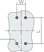 |
Width(W) | 30 | 60 | 30 | 60 | 30 | 60 | 35 | 70 | 35 | 70 | 35 | 70 | 44 | 94 | 44 | 94 | 44 | 94 | 140 | 140 | 140 | 140 | 140 | 140 |
| Length(L) | 129 | 129 | 129 | 129 | 129 | 129 | 126 | 126 | 126 | 126 | 126 | 126 | 194 | 194 | 194 | 194 | 194 | 194 | 243 | 243 | 243 | 243 | 243 | 243 | ||
| 5.5 | 5.5 | 5.5 | 5.5 | 5.5 | 5.5 | 5.5 | 5.5 | 5.5 | 5.5 | 5.5 | 5.5 | 7 | 7 | 7 | 7 | 7 | 7 | |||||||||
| Optional accessories | ||||||||||||||||||||||||||
| Alarm contact | 08 | □ | □ | □ | □ | □ | □ | □ | □ | □ | □ | □ | □ | □ | □ | □ | □ | □ | □ | □ | □ | □ | □ | □ | □ | |
| Shunt release | 10 | □ | □ | □ | □ | □ | □ | □ | □ | □ | □ | □ | □ | □ | □ | □ | □ | □ | □ | □ | □ | □ | □ | □ | □ | |
| Auxiliary contact | 20 | □ | □ | □ | □ | □ | □ | □ | □ | □ | □ | □ | □ | □ | □ | □ | □ | □ | □ | □ | □ | □ | □ | □ | □ | |
| Auxiliary contact+Alarm contact | 28 | □ | □ | □ | □ | □ | □ | □ | □ | □ | □ | □ | □ | □ | □ | □ | □ | □ | □ | □ | □ | □ | □ | □ | □ | |
| Back-panel wiring | R | □ | □ | □ | □ | □ | □ | □ | □ | □ | □ | □ | □ | □ | □ | □ | □ | □ | □ | □ | □ | □ | □ | □ | □ | |
| Plug in back wiring | PR | □ | □ | □ | □ | □ | □ | □ | □ | □ | □ | □ | □ | □ | □ | □ | □ | □ | □ | □ | □ | □ | □ | □ | □ | |


