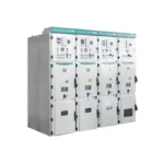
KYN28A-12 Metal Clad Switchgear
KYN28A-12 Metal clad switchgear (hereinafter referred to as switchgear) is suitable for...
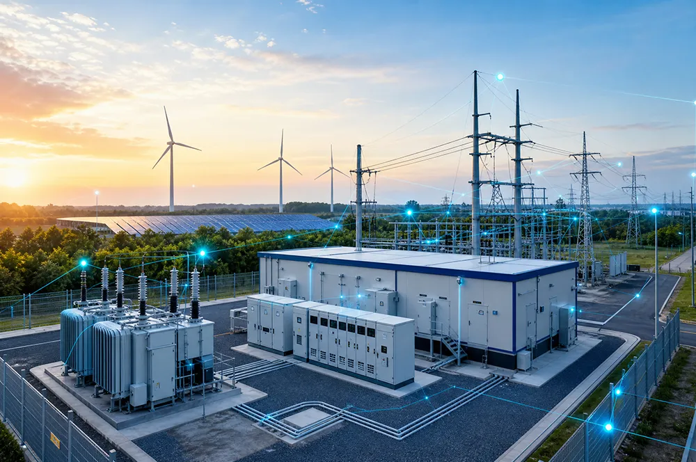
From transformers and switchgear to ring main units, substations, circuit breakers and smart components, Jubang provides integrated product support for power distribution projects.
Discover Jubang’s strengths in technology R&D, quality testing and smart manufacturing, supporting reliable electrical equipment and efficient power distribution solutions for global customers.

From technical consultation and OEM/ODM customization to EPC support, smart O&M, delivery documentation and after-sales service, Jubang supports your project at every stage.
Explore Jubang Group’s development history, intelligent manufacturing base, R&D platforms, CNAS-accredited laboratory and global project service capabilities.

High Sealing Performance
Energy Saving & Reduced Loss
Low Noise
Compact Structure
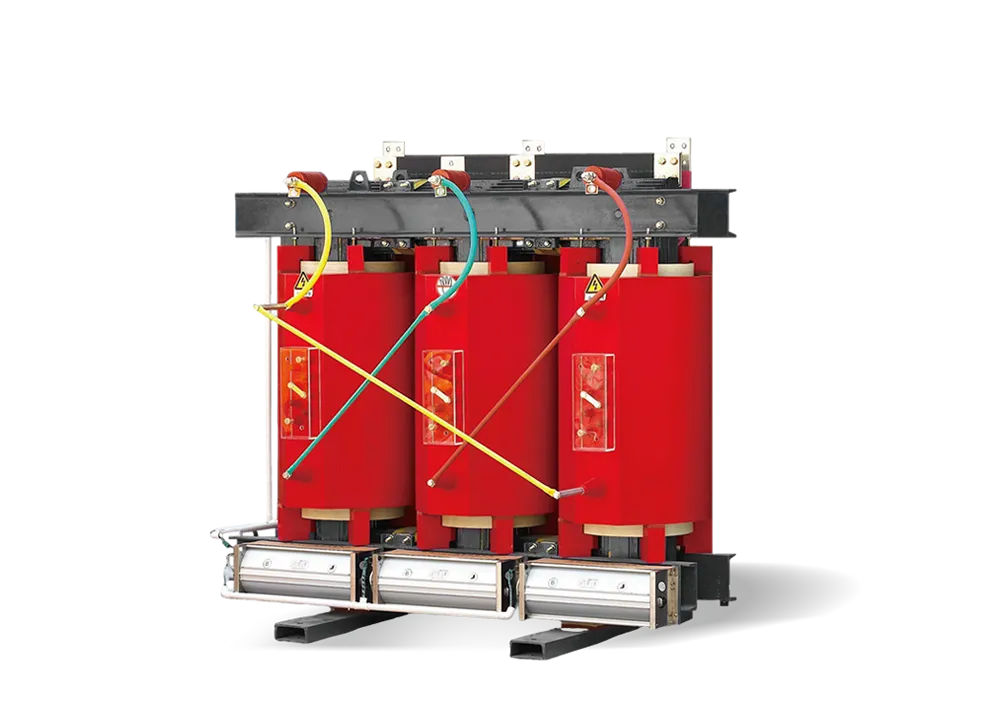
The three-phase oil-immersed power transformers produced by our company adopt a new insulation structure, which improves short-circuit resistance. The iron core is made of high-quality cold-rolled silicon steel sheets. The high-voltage winding is made of high-quality oxygen-free copper conductors and adopts a multilayer cylindrical structure. All fasteners are specially treated to prevent loosening. The product features high efficiency and low loss, which can significantly reduce power consumption and operating costs. It offers remarkable economic and social benefits and is a high-tech product widely promoted by the state.
Based on traditional technology and mature manufacturing processes, our company has carried out multiple improvements, including:
① Spiral windings with oil ducts for better internal heat dissipation.
② Improved effective support at the winding ends for stronger short-circuit resistance.
③ A new lifting structure and body positioning design for improved reliability during long-distance transportation and operation.
④ Various unique and reliable structural designs to better meet customer needs.
⑤ Advanced winding technology for higher technical performance.
⑥ A fully sealed tank structure that isolates the transformer from air, preventing oil oxidation and insulation moisture, thereby enhancing operational reliability and enabling maintenance-free normal operation.
All Raw Materials Are Strictly Tested, All material suppliers have passed strict audits under the ISO 9000 quality management system.
① Oxygen-free copper conductors with lower resistivity are used, and after a series of surface treatments, they are smoother and burr-free, resulting in lower load loss and more reliable electrical performance.
② High-quality silicon steel sheets with lower unit loss are used to reduce no-load loss.
③ High-quality laminated insulation components are used to ensure that insulation does not crack or shift under short-circuit conditions.
④ Transformer oil is deeply filtered, ensuring lower moisture, gas, and impurity levels for more reliable operation.
⑤ High-quality rubber sealing materials are used to effectively prevent aging and oil leakage.
Altitude:
Not exceeding 1000 m
Ambient Temperature:
Maximum temperature: 45℃
Minimum temperature: -25℃
Maximum daily average temperature: 25℃
Maximum annual average temperature: 30℃
Annual average temperature: 20℃
Power Supply Conditions:
The waveform of the supply voltage shall be approximately sinusoidal.
For three-phase transformers, the three-phase supply voltage should be approximately symmetrical.
Installation Environment:
The installation site should be free from obvious contamination.
Seismic Resistance:
Ground acceleration caused by earthquakes:
Horizontal direction: ≤3 m/s²
Vertical direction: ≤1.5 m/s²
If any special operating conditions beyond the normal service conditions are required, please specify them during inquiry and ordering.
GB/T1094.1 GB/T1094.2 GB/T1094.3 GB/T1094.5 GB/T25289 GB/T25438
GB/T6451 GB/T7595 GB20052 JB/T3837 JB/T10088
The transformers manufactured by our company comply with the latest editions of the above standards.
When placing an order, please provide the following information:
① Transformer model
② Rated capacity
③ Rated voltage of high-voltage and low-voltage sides
④ High-voltage tapping range
⑤ Phase number
⑥ Frequency
⑦ Vector group designation
![]()
![]()
![]()
![]()
Technical Parameters of 6kV/10kV Class S11 Series Oil-Immersed Three-Phase On-Load Tap-Changing Distribution Transformers
| Rated Capacity(kVA) | Voltage Combination(kV) | Vector Group | Loss(kW) | No-load Current(%) | Short-circuit Impedance(%) | Weight(kg) | Overall Dimensions(mm) L×W×H |
Track Gauge(Longitudinal/Transverse) | |||||
| HV | HV Tapping Range(%) | LV | No-load | Load | Active Part Weight | Oil Weight | Total Weight | ||||||
| 30 | 6 6.3 10 10.5 |
±2×2.5 ±5 |
0.4 | Dyn11 Yzn11 Yyn0 |
0.100 | 0.630/0.600 | 1.5 | 4.0 | 135 | 55 | 325 | 680×480×846 | 550/400 |
| 50 | 0.130 | 0.910/0.870 | 1.3 | 210 | 75 | 435 | 765×690×876 | 550/400 | |||||
| 63 | 0.150 | 1.090/1.040 | 1.2 | 245 | 85 | 490 | 795×645×915 | 550/400 | |||||
| 80 | 0.180 | 1.310/1.250 | 1.2 | 290 | 90 | 550 | 825×660×925 | 550/550 | |||||
| 100 | 0.200 | 1.580/1.500 | 1.1 | 315 | 95 | 590 | 810×770×890 | 550/550 | |||||
| 125 | 0.240 | 1.890/1.800 | 1.1 | 365 | 100 | 660 | 825×800×960 | 550/550 | |||||
| 160 | 0.280 | 2.310/2.200 | 1.0 | 440 | 115 | 720 | 1115×735×985 | 550/550 | |||||
| 200 | 0.340 | 2.730/2.600 | 1.0 | 490 | 160 | 790 | 1186×815×1050 | 550/550 | |||||
| 250 | 0.400 | 3.200/3.050 | 0.9 | 600 | 150 | 960 | 1290×860×1050 | 660/660 | |||||
| 315 | 0.480 | 3.830/3.650 | 0.9 | 710 | 180 | 1120 | 1350×920×1090 | 660/660 | |||||
| 400 | 0.570 | 4.520/4.300 | 0.8 | 4.5 | 920 | 210 | 1440 | 1485×1030×1120 | 660/660 | ||||
| 500 | 0.680 | 5.410/5.150 | 0.8 | 1050 | 320 | 1800 | 1470×1030×1160 | 660/660 | |||||
| 630 | 0.810 | 6.200 | 0.6 | 1130 | 260 | 1770 | 1550×1045×1225 | 660/660 | |||||
| 800 | 0.980 | 7.500 | 0.6 | 1340 | 290 | 2060 | 1730×1220×1285 | 820/820 | |||||
| 1000 | 1.150 | 10.300 | 0.6 | 1440 | 420 | 2505 | 1670×1160×1375 | 820/820 | |||||
| 1250 | 1.360 | 12.000 | 0.5 | 1750 | 480 | 2970 | 1750×1240×1425 | 820/820 | |||||
| 1600 | 1.640 | 14.500 | 0.5 | 2240 | 600 | 3950 | 1860×1260×1485 | 820/820 | |||||
| 2000 | 1.940 | 18.300 | 0.4 | 5.0 | 2575 | 635 | 4305 | 1990×1315×1620 | 820/820 | ||||
| 2500 | 2.290 | 21.200 | 0.4 | 3270 | 815 | 5440 | 2065×1360×1750 | 1070/1070 | |||||
Note:
① For three-phase transformers with a rated capacity of 500 KVA and below, the load loss above the diagonal line in the table applies to Dyn11 or Yzn11 vector groups, while the load loss below the diagonal line applies to the Yyn0 vector group.
② The overall dimensions provided are for reference during selection only. The final dimensions shall be subject to the actual product outline drawing.
Technical Parameters of 6kV/10kV Class S11 Series Oil-Immersed Three-Phase Double-Winding Non-Excitation Tap-Changing Distribution Transformers
| Rated Capacity(kVA) | Voltage Combination(kV) | Vector Group | Loss(kW) | No-load Current(%) | Short-circuit Impedance(%) | Weight(kg) | Overall Dimensions(mm) L×W×H |
Track Gauge(Longitudinal/Transverse) | |||||
| HV | HV Tapping Range(%) | LV | No-load | Load | Active Part Weight | Oil Weight | Total Weight | ||||||
| 200 | 6 6.3 10 10.5 |
±2×2.5 ±5 |
3 3.15 6.3 |
Yd11 Dy11 |
0.34 | 3.15 | 1.8 | 4.5 | 650 | 160 | 1000 | 1180×740×1270 | 660/660 |
| 250 | 0.40 | 3.60 | 1.7 | 770 | 200 | 1190 | 1230×780×1340 | ||||||
| 315 | 0.48 | 4.30 | 1.6 | 900 | 215 | 1360 | 1260×810×1370 | ||||||
| 400 | 0.57 | 5.20 | 1.5 | 1080 | 260 | 1650 | 1380×900×1390 | ||||||
| 500 | 0.68 | 6.20 | 1.4 | 1250 | 280 | 1890 | 1400×920×1450 | ||||||
| 630 | 0.82 | 6.92 | 0.6 | 5.5 | 1470 | 340 | 2245 | 1580×1020×1430 | 820/820 | ||||
| 800 | 1.00 | 8.46 | 0.6 | 1735 | 385 | 2645 | 1665×1070×1520 | ||||||
| 1000 | 1.18 | 9.91 | 0.6 | 1910 | 430 | 2980 | 1740×1160×1550 | ||||||
| 1250 | 1.40 | 11.70 | 0.5 | 2210 | 590 | 3640 | 1820×1210×1740 | ||||||
| 1600 | 1.68 | 14.10 | 0.4 | 2640 | 680 | 4270 | 1840×1240×1860 | ||||||
| 2000 | 2.01 | 16.90 | 0.4 | 2890 | 725 | 4775 | 2210×1920×1970 | ||||||
| 2500 | 2.37 | 19.60 | 0.4 | 3460 | 910 | 5710 | 2260×1970×1995 | 1070/1070 | |||||
| 3150 | 2.80 | 23.00 | 0.4 | 4230 | 1350 | 7085 | 2320×2280×2360 | ||||||
| 4000 | 10.5 10 |
6.3 3.15 |
3.45 | 27.30 | 0.4 | 5025 | 1675 | 8150 | 2460×2480×2475 | ||||
| 5000 | 4.10 | 31.30 | 0.4 | 6020 | 1940 | 9610 | 2575×2640×2590 | ||||||
| 6300 | 4.89 | 35.0 | 0.4 | 8125 | 2550 | 12660 | 2640×2820×2810 | ||||||
| 8000 | 6.52 | 40.5 | 0 | 9620 | 2780 | 15100 | 2710×2840×3040 | 1475/1475 | |||||
| 10000 | 7.70 | 47.7 | 0.55 | 11660 | 3070 | 17480 | 2850×2880×3265 | ||||||
Note:
①The overall dimensions provided are for reference during model selection only. The final dimensions shall be subject to the product outline drawing.
Technical Data – 6kV/10kV S13 Series Oil-Immersed Three-Phase Distribution Transformer
| Rated Capacity(kVA) | Voltage Combination(kV) | Vector Group | Loss(kW) | No-load Current(%) | Short-circuit Impedance(%) | Weight(kg) | Overall Dimensions(mm) L×W×H |
Track Gauge(Longitudinal/Transverse) | |||||
| HV | HV Tapping Range(%) | LV | No-load | Load | Active Part Weight | Oil Weight | Total Weight | ||||||
| 30 | 6 6.3 10 10.5 |
±2×2.5 ±5 |
0.4 | Dyn11 Yzn11 Yyn0 |
0.080 | 0.630/0.600 | 1.2 | 4.0 | 140 | 60 | 280 | 700×545×855 | 550/400 |
| 50 | 0.100 | 0.910/0.870 | 1.04 | 210 | 80 | 370 | 750×645×915 | 550/400 | |||||
| 63 | 0.110 | 1.090/1.040 | 0.96 | 240 | 90 | 440 | 790×645×915 | 550/400 | |||||
| 80 | 0.130 | 1.310/1.250 | 0.96 | 260 | 90 | 480 | 805×706×930 | 550/550 | |||||
| 100 | 0.150 | 1.580/1.500 | 0.88 | 350 | 110 | 600 | 850×685×1075 | 550/550 | |||||
| 125 | 0.170 | 1.890/1.800 | 0.88 | 380 | 110 | 645 | 850×790×975 | 550/550 | |||||
| 160 | 0.200 | 2.310/2.200 | 0.80 | 500 | 130 | 790 | 880×860×1050 | 550/550 | |||||
| 200 | 0.240 | 2.730/2.600 | 0.80 | 540 | 160 | 870 | 1180×791×090 | 550/550 | |||||
| 250 | 0.290 | 3.200/3.050 | 0.72 | 670 | 170 | 1050 | 1270×850×1140 | 660/660 | |||||
| 315 | 0.340 | 3.830/3.650 | 0.72 | 750 | 180 | 1150 | 1320×900×1160 | 660/660 | |||||
| 400 | 0.410 | 4.520/4.300 | 0.64 | 905 | 210 | 1370 | 1390×950×1215 | 660/660 | |||||
| 500 | 0.480 | 5.410/5.150 | 0.64 | 1120 | 240 | 1680 | 1420×950×1280 | 660/660 | |||||
| 630 | 0.570 | 6.200 | 0.48 | 4.5 | 1330 | 280 | 1960 | 1490×1000×1340 | 660/660 | ||||
| 800 | 0.700 | 7.500 | 0.48 | 1400 | 300 | 2150 | 1640×1155×1350 | 820/820 | |||||
| 1000 | 0.830 | 10.300 | 0.48 | 1510 | 350 | 2410 | 1660×1155×1380 | 820/820 | |||||
| 1250 | 0.970 | 12.000 | 0.40 | 1720 | 440 | 2860 | 1720×1250×1480 | 820/820 | |||||
| 1600 | 1.17 | 14.500 | 0.40 | 2285 | 590 | 3745 | 1840×1340×1560 | 820/820 | |||||
| 2000 | 1.36 | 18.300 | 0.32 | 5.0 | 2554 | 730 | 4289 | 2010×1370×1660 | 820/820 | ||||
| 2500 | 1.60 | 21.200 | 0.32 | 2995 | 810 | 5170 | 2020×1370×1850 | 1070/1070 | |||||
Note:
① For three-phase transformers with a rated capacity of 500 KVA and below, the load loss above the diagonal line in the table applies to Dyn11 or Yzn11 vector groups, while the load loss below the diagonal line applies to the Yyn0 vector group.
② The overall dimensions provided are for reference during model selection only. The final dimensions shall be subject to the product outline drawing.
Technical Data – 6kV/10kV S14 Series Oil-Immersed Three-Phase Distribution Transformer
| Rated Capacity(kVA) | Voltage Combination(kV) | Vector Group | No-load Loss(kW) | Load Loss(kW) | No-load Current(%) | Short-circuit Impedance(%) | ||
| HV(kV) | HV Tapping Range(%) | LV(kV) | ||||||
| 30 | 6 6.3 10 10.5 |
±2×2.5 ±5 |
0.4 | Dyn11 Yzn11 Yyn0 |
0.080 | 0.505/0.480 | 1.2 | 4.0 |
| 50 | 0.100 | 0.730/0.695 | 1.04 | |||||
| 63 | 0.110 | 0.870/0.830 | 0.96 | |||||
| 80 | 0.130 | 1.05/1.00 | 0.96 | |||||
| 100 | 0.150 | 1.26/1.20 | 0.88 | |||||
| 125 | 0.170 | 1.51/1.44 | 0.88 | |||||
| 160 | 0.200 | 1.85/1.76 | 0.8 | |||||
| 200 | 0.240 | 2.18/2.08 | 0.8 | |||||
| 250 | 0.290 | 2.56/2.44 | 0.72 | |||||
| 315 | 0.340 | 3.06/2.92 | 0.72 | |||||
| 400 | 0.410 | 3,61/3.44 | 0.64 | |||||
| 500 | 0.480 | 4.33/4.12 | 0.64 | |||||
| 630 | Dyn11 Yyn0 |
0.570 | 4.96 | 0.48 | 4.5 | |||
| 800 | 0.700 | 6.00 | 0.48 | |||||
| 1000 | 0.830 | 8.24 | 0.48 | |||||
| 1250 | 0.970 | 9.60 | 0.4 | |||||
| 1600 | 1.17 | 11.6 | 0.4 | |||||
| 2000 | 1.55 | 14.6 | 0.32 | 5.0 | ||||
| 2500 | 1.83 | 16.9 | 0.32 | |||||
Note:
① For three-phase transformers with a rated capacity of 500 KVA and below, the load loss above the diagonal line in the table applies to Dyn11 or Yzn11 vector groups, while the load loss below the diagonal line applies to the Yyn0 vector group.
Technical Data – 6kV/10kV SZ11 Series Oil-Immersed Three-Phase Distribution Transformer (On-Load Tap Changer)
| Rated Capacity(kVA) | Voltage Combination(kV) | Vector Group | No-load Loss(kW) | Load Loss(kW) | No-load Current(%) | Short-circuit Impedance(%) | ||
| HV(kV) | HV Tapping Range(%) | LV(kV) | ||||||
| 200 | 6 6.3 10 10.5 |
±4×2.5 | 0.4 | Dyn11 Yyn0 |
0.38 | 2.90 | 1.0 | 4.0 |
| 250 | 0.44 | 3.42 | 0.90 | |||||
| 315 | 0.53 | 4.10 | 0.90 | |||||
| 400 | 0.64 | 4.95 | 0.80 | |||||
| 500 | 0.76 | 5.89 | 0.80 | |||||
| 630 | 0.96 | 7.26 | 0.60 | |||||
| 800 | 1.12 | 8.89 | 0.60 | 4.5 | ||||
| 1000 | 1.36 | 10.4 | 0.60 | |||||
| 1250 | 1.56 | 12.3 | 0.50 | |||||
| 1600 | 1.92 | 14.7 | 0.50 | |||||
| 2000 | 2.27 | 18.6 | 0.40 | 5.0 | ||||
| 2500 | 2.68 | 21.6 | 0.40 | |||||
Technical Data – 6kV/10kV SZ12 Series Oil-Immersed Three-Phase Distribution Transformer (On-Load Tap Changer)
| Rated Capacity(kVA) | Voltage Combination(kV) | Vector Group | No-load Loss(kW) | Load Loss(kW) | No-load Current(%) | Short-circuit Impedance(%) | ||
| HV(kV) | HV Tapping Range(%) | LV(kV) | ||||||
| 200 | 6 6.3 10 10.5 |
±4×2.5 | 0.4 | Dyn11 Yyn0 |
0.34 | 2.90 | 1.0 | 4.0 |
| 250 | 0.39 | 3.42 | 0.90 | |||||
| 315 | 0.47 | 4.10 | 0.90 | |||||
| 400 | 0.57 | 4.95 | 0.80 | |||||
| 500 | 0.68 | 5.89 | 0.80 | |||||
| 630 | 0.86 | 7.26 | 0.60 | 4.5 | ||||
| 800 | 1.00 | 8.89 | 0.60 | |||||
| 1000 | 1.22 | 10.4 | 0.60 | |||||
| 1250 | 1.40 | 12.3 | 0.50 | |||||
| 1600 | 1.72 | 14.7 | 0.50 | |||||
| 2000 | 2.04 | 18.6 | 0.40 | 5.0 | ||||
| 2500 | 2.41 | 21.6 | 0.40 | |||||
Technical Data – 6kV/10kV SZ13 Series Oil-Immersed Three-Phase Distribution Transformer (On-Load Tap Changer)
| Rated Capacity(kVA) | Voltage Combination(kV) | Vector Group | No-load Loss(kW) | Load Loss(kW) | No-load Current(%) | Short-circuit Impedance(%) | ||
| HV(kV) | HV Tapping Range(%) | LV(kV) | ||||||
| 200 | 6 6.3 10 10.5 |
±4×2.5 | 0.4 | Dyn11 Yyn0 |
0.305 | 2.90 | 0.8 | 4.0 |
| 250 | 0.350 | 3.42 | 0.72 | |||||
| 315 | 0.425 | 4.10 | 0.72 | |||||
| 400 | 0.510 | 4.95 | 0.64 | |||||
| 500 | 0.610 | 5.89 | 0.64 | |||||
| 630 | 0.770 | 7.26 | 0.48 | 4.5 | ||||
| 800 | 0.895 | 8.89 | 0.48 | |||||
| 1000 | 1.09 | 10.4 | 0.48 | |||||
| 1250 | 1.25 | 12.3 | 0.4 | |||||
| 1600 | 1.54 | 14.7 | 0.4 | |||||
| 2000 | 1.82 | 18.6 | 0.32 | 5.0 | ||||
| 2500 | 2.14 | 21.6 | 0.32 | |||||
Technical Data – 6kV/10kV S13 Series Grade 3 Energy-Efficient Oil-Immersed Three-Phase Distribution Transformer
| Rated Capacity(kVA) | Voltage Combination(kV) | Vector Group | Loss(kW) | No-load Current(%) | Short-circuit Impedance(%) | Weight(kg) | Overall Dimensions(mm) L×W×H |
Track Gauge(Longitudinal/Transverse) | |||||
| HV | HV Tapping Range(%) | LV | No-load | Load Loss | Active Part Weight | Oil Weight | Total Weight | ||||||
| 30 | 6 6.3 10 10.5 |
±2×2.5 ±5 |
0.4 | Dyn11 Yzn11 Yyn0 |
0.080 | 0.630/0.600 | 1.2 | 4.0 | 140 | 70 | 320 | 745×555×830 | 550/400 |
| 50 | 0.100 | 0.910/0.870 | 1.04 | 205 | 75 | 390 | 775×595×890 | 550/400 | |||||
| 63 | 0.110 | 1.090/1.040 | 0.96 | 240 | 85 | 450 | 790×640×930 | 550/400 | |||||
| 80 | 0.130 | 1.310/1.250 | 0.96 | 290 | 95 | 520 | 857×675×950 | 550/550 | |||||
| 100 | 0.150 | 1.580/1.500 | 0.88 | 340 | 100 | 576 | 845×720×950 | 550/550 | |||||
| 125 | 0.170 | 1.890/1.800 | 0.88 | 390 | 110 | 650 | 850×770×990 | 550/550 | |||||
| 160 | 0.200 | 2.310/2.200 | 0.8 | 470 | 150 | 760 | 1130×770×1013 | 550/550 | |||||
| 200 | 0.240 | 2.730/2.600 | 0.8 | 540 | 135 | 861 | 1160×780×1160 | 550/550 | |||||
| 250 | 0.290 | 3.200/3.050 | 0.72 | 670 | 160 | 1030 | 1220×810×1111 | 660/660 | |||||
| 315 | 0.340 | 3.830/3.650 | 0.72 | 750 | 173 | 1160 | 1280×880×1150 | 660/660 | |||||
| 400 | 0.410 | 4.520/4.300 | 0.64 | 910 | 210 | 1390 | 1320×900×1196 | 660/660 | |||||
| 500 | 0.480 | 5.410/5.150 | 0.64 | 1070 | 230 | 1650 | 1420×980×1240 | 660/660 | |||||
| 630 | 0.570 | 6.200 | 0.48 | 4.5 | 1310 | 290 | 1960 | 1510×1010×1310 | 660/660 | ||||
| 800 | 0.700 | 7.500 | 0.48 | 1550 | 320 | 2320 | 1640×1120×1335 | 820/820 | |||||
| 1000 | 0.830 | 10.300 | 0.48 | 1595 | 360 | 2550 | 1675×1145×1365 | 820/820 | |||||
| 1250 | 0.970 | 12.000 | 0.4 | 2110 | 500 | 3370 | 1820×1260×1492 | 820/820 | |||||
| 1600 | 1.17 | 14.500 | 0.4 | 2635 | 600 | 4190 | 1940×1300×1625 | 820/820 | |||||
| 2000 | 1.36 | 18.300 | 0.32 | 5.0 | 2700 | 755 | 4720 | 2000×1345×1700 | 820/820 | ||||
| 2500 | 1.60 | 21.200 | 0.32 | 3240 | 835 | 5460 | 2030×1360×1900 | 1070/1070 | |||||
Notes:
① For three-phase transformers with a rated capacity of 500 kVA and below, the load loss above the diagonal line in the table applies to Dyn11 or Yzn11 vector groups, while the load loss below the diagonal line applies to the Yyn0 vector group.
② The load loss values comply with the requirements for Grade 3 energy efficiency specified in Table 1 of GB20052-2020.
③ The overall dimensions provided are for reference during model selection only. The final dimensions shall be subject to the product outline drawing.
Technical Data – 6kV/10kV S20 Series Grade 2 Energy-Efficient Oil-Immersed Three-Phase Distribution Transformer
| Rated Capacity(kVA) | Voltage Combination(kV) | Vector Group | Loss(kW) | No-load Current(%) | Short-circuit Impedance(%) | Weight(kg) | Overall Dimensions(mm) L×W×H |
Track Gauge(Longitudinal/Transverse) | |||||
| HV | HV Tapping Range(%) | LV | No-load | Load Loss | Active Part Weight | Oil Weight | Total Weight | ||||||
| 30 | 6 6.3 10 10.5 |
±2×2.5 ±5 |
0.4 | Dyn11 Yzn11 Yyn0 |
0.070 | 0.505/0.480 | 1.2 | 4.0 | 180 | 70 | 370 | 780×355×860 | 550/400 |
| 50 | 0.090 | 0.730/0.695 | 1.04 | 288 | 85 | 510 | 860×365×940 | 550/400 | |||||
| 63 | 0.100 | 0.870/0.830 | 0.96 | 335 | 95 | 590 | 865×370×960 | 550/400 | |||||
| 80 | 0.115 | 1.050/1.000 | 0.96 | 380 | 100 | 650 | 880×380×1015 | 550/550 | |||||
| 100 | 0.135 | 1.265/1.200 | 0.88 | 440 | 115 | 735 | 920×580×1020 | 550/550 | |||||
| 125 | 0.150 | 1.510/1.440 | 0.88 | 525 | 120 | 850 | 930×675×1080 | 550/550 | |||||
| 160 | 0.180 | 1.850/1.760 | 0.8 | 630 | 150 | 1010 | 965×680×1160 | 550/550 | |||||
| 200 | 0.215 | 2.185/2.080 | 0.8 | 760 | 165 | 1170 | 1010×750×1180 | 550/550 | |||||
| 250 | 0.260 | 2.560/2.440 | 0.72 | 865 | 180 | 1290 | 1015×750×1190 | 660/660 | |||||
| 315 | 0.305 | 3.065/2.920 | 0.72 | 1050 | 210 | 1560 | 1095×780×1230 | 660/660 | |||||
| 400 | 0.370 | 3.615/3.440 | 0.64 | 1100 | 230 | 1675 | 1100×900×1260 | 660/660 | |||||
| 500 | 0.430 | 4.330/4.120 | 0.64 | 1420 | 265 | 2090 | 1160×940×1310 | 660/660 | |||||
| 630 | 0.510 | 4.960 | 0.48 | 4.5 | 1705 | 300 | 2450 | 1250×980×1345 | 660/660 | ||||
| 800 | 0.630 | 6.000 | 0.48 | 1895 | 320 | 2700 | 1260×990×1360 | 820/820 | |||||
| 1000 | 0.745 | 8.240 | 0.48 | 2080 | 360 | 3045 | 1615×1095×1450 | 820/820 | |||||
| 1250 | 0.870 | 9.600 | 0.4 | 2550 | 470 | 3790 | 1705×1100×1520 | 820/820 | |||||
| 1600 | 1.050 | 11.600 | 0.4 | 2910 | 575 | 4340 | 1800×1145×1700 | 820/820 | |||||
| 2000 | 1.225 | 14.640 | 0.32 | 5.0 | 3525 | 595 | 5000 | 1925×1180×1750 | 820/820 | ||||
| 2500 | 1.440 | 14.840 | 0.32 | 4860 | 690 | 6490 | 1945×1230×1990 | 1070/1070 | |||||
Notes:
① For three-phase transformers with a rated capacity of 500 kVA and below, the load loss above the diagonal line in the table applies to Dyn11 or Yzn11 vector groups, while the load loss below the diagonal line applies to the Yyn0 vector group.
② The load loss values comply with the requirements for Grade 3 energy efficiency specified in Table 1 of GB20052-2020.
③ The overall dimensions provided are for reference during model selection only. The final dimensions shall be subject to the product outline drawing.
Technical Data – 6kV/10kV S22 Series Grade 1 Energy-Efficient Oil-Immersed Three-Phase Distribution Transformer
| Rated Capacity(kVA) | Voltage Combination(kV) | Vector Group | Loss(kW) | No-load Current(%) | Short-circuit Impedance(%) | Weight(kg) | Overall Dimensions(mm) L×W×H |
Track Gauge(Longitudinal/Transverse) | |||||
| HV | HV Tapping Range(%) | LV | No-load | Load Loss | Active Part Weight | Oil Weight | Total Weight | ||||||
| 30 | 6 6.3 10 10.5 |
±2×2.5 ±5 |
0.4 | Dyn11 Yzn11 Yyn0 |
0.065 | 0.455/0.430 | 1.2 | 4.0 | 196 | 65 | 385 | 790×345×870 | 550/400 |
| 50 | 0.080 | 0.655/0.625 | 1.04 | 320 | 85 | 560 | 845×370×960 | 550/400 | |||||
| 63 | 0.090 | 0.785/0.745 | 0.96 | 365 | 90 | 600 | 865×380×1000 | 550/400 | |||||
| 80 | 0.105 | 0.945/0.900 | 0.96 | 430 | 100 | 685 | 895×390×1035 | 550/550 | |||||
| 100 | 0.120 | 1.140/1.080 | 0.88 | 520 | 115 | 810 | 925×515×1045 | 550/550 | |||||
| 125 | 0.135 | 1.360/1.295 | 0.88 | 590 | 120 | 900 | 945×565×1085 | 550/550 | |||||
| 160 | 0.160 | 1.665/1.585 | 0.8 | 715 | 150 | 1075 | 985×570×1120 | 550/550 | |||||
| 200 | 0.190 | 1.970/1.870 | 0.8 | 895 | 160 | 1300 | 1015×605×1150 | 550/550 | |||||
| 250 | 0.230 | 2.300/2.195 | 0.72 | 985 | 180 | 1405 | 1030×640×1200 | 660/660 | |||||
| 315 | 0.270 | 2.760/2.630 | 0.72 | 1200 | 215 | 1725 | 1120×750×1245 | 660/660 | |||||
| 400 | 0.330 | 3.250/3.095 | 0.64 | 1280 | 220 | 1845 | 1150×825×1300 | 660/660 | |||||
| 500 | 0.385 | 3.900/3.710 | 0.64 | 1545 | 240 | 2150 | 1205×845×1400 | 660/660 | |||||
| 630 | 0.460 | 4.460 | 0.48 | 4.5 | 1890 | 270 | 2580 | 1275×900×1500 | 660/660 | ||||
| 800 | 0.560 | 5.400 | 0.48 | 2180 | 335 | 2990 | 1365×950×1520 | 820/820 | |||||
| 1000 | 0.665 | 7.415 | 0.48 | 2260 | 400 | 3255 | 1430×1050×1550 | 820/820 | |||||
| 1250 | 0.780 | 8.640 | 0.4 | 2890 | 470 | 4060 | 1480×1075×1590 | 820/820 | |||||
| 1600 | 0.940 | 10.440 | 0.4 | 3260 | 510 | 4600 | 1520×1115×1725 | 820/820 | |||||
| 2000 | 1.085 | 13.180 | 0.32 | 5.0 | 4070 | 650 | 5600 | 1565×1235×1830 | 820/820 | ||||
| 2500 | 1.280 | 13.360 | 0.32 | 5615 | 670 | 7195 | 1680×1290×2110 | 1070/1070 | |||||
Notes:
① For three-phase transformers with a rated capacity of 500 kVA and below, the load loss above the diagonal line in the table applies to Dyn11 or Yzn11 vector groups, while the load loss below the diagonal line applies to the Yyn0 vector group.
② The load loss values comply with the requirements for Grade 1 energy efficiency specified in Table 1 of GB20052-2020.
③ The overall dimensions provided are for reference during model selection only. The final dimensions shall be subject to the product outline drawing.


