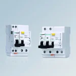
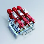
FZ (R)N25-12D-T Series indoor high-voltage AC compressed air load switch fuse combination device
• It is currently the most advanced medium voltage vacuum load switch...
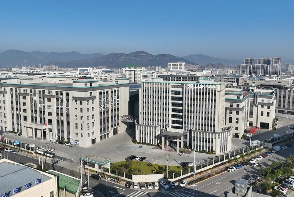
From transformers and switchgear to ring main units, substations, circuit breakers and smart components, Jubang provides integrated product support for power distribution projects.
Discover Jubang’s strengths in technology R&D, quality testing and smart manufacturing, supporting reliable electrical equipment and efficient power distribution solutions for global customers.
From technical consultation and OEM/ODM customization to EPC support, smart O&M, delivery documentation and after-sales service, Jubang supports your project at every stage.
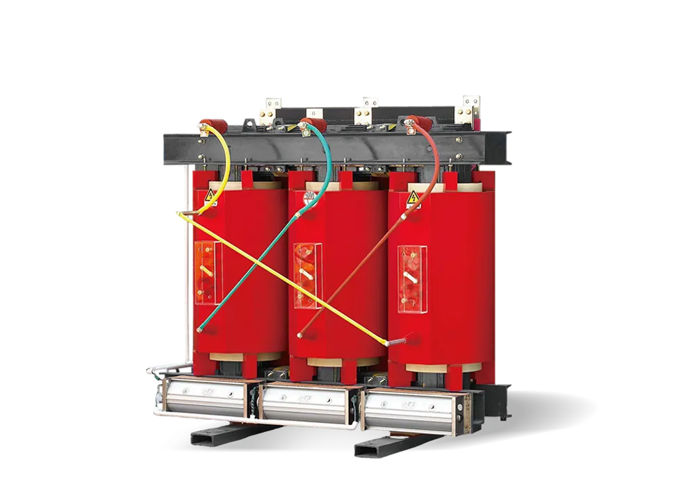
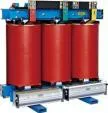
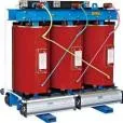
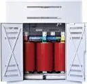
SCZB11 Series 6-10KV dry-type transformers are crucial electrical equipment in medium-voltage power systems, primarily functioning to regulate voltage and distribute electrical power. They step down high-voltage electricity (from transmission networks or large power sources) to 6-10KV medium voltage for safe delivery to various users, or step up low-voltage power from generators or local grids to 6-10KV for integration into the main power network. This voltage conversion ensures efficient power transmission and utilization while maintaining electrical safety.
| S | C | Z | (B) | 10 – |
□ / |
□ | |
| ↓ | ↓ | ↓ | ↓ | ↓ | ↓ | ↓ | |
| Three-phase | Solid
forming |
On load voltage
regulation |
Low voltage
foil coil |
Loss level | Rated capacity
kV.A |
System nominal
voltage kV |
|
| Epoxy resin
casting |
10 11 |
12 | |||||
1.1 Product features
Resin insulated dry transformer is the introduction of foreign advanced technology, independent development of SC(B)10, SC(B)11, SC(B)12 and SC(B)13 series with packing thin insulation dry transformer, because the coil is wrapped by epoxy resin, so flame resistant, fire, explosion-proof, maintenance-free, pollution-free, small size, can be directly installed in the load center. At the same time, the scientific and reasonable design and pouring process make the local discharge of the product smaller, low noise, strong heat dissipation capacity, can run for a long time under 140% rated load under forced air cooling conditions, and equipped with intelligent temperature controller, with fault alarm, overtemperature alarm, overtemperature trip and black gate sub-functions, and connected to the computer through RS485 serial interface. Can be centrally monitored and controlled. Because of the above characteristics of our dry transformer, it is widely used in power transmission and transformation systems, such as hotels, airports, high-rise buildings, commercial centers, residential areas and other important places, as well as subways, smelting power plants, ships, offshore drilling platforms and other harsh environments.
1.2 Iron core
The iron core is made of imported high-quality cold-rolled silicon steel sheets, with a fully inclined seam structure. The core column is tied with F-grade weft free adhesive tape, and the surface of the iron core is sealed with insulating resin paint to prevent moisture and rust, reducing no-load loss, no-load current, and iron core noise. The clamps and fasteners have undergone special surface treatment, further improving the appearance quality of the product.
1.3 High voltage winding
The high-voltage winding is vacuum cast with epoxy resin filled with fillers, which greatly reduces partial discharge and improves the electrical strength of the coil. The inner and outer walls of the winding are filled with fiberglass mesh plates, enhancing the mechanical strength of the coil and improving the product’s ability to withstand sudden short circuits. The coil never cracks.
1.4 Low voltage winding
The low-voltage winding adopts a foil structure, which solves the problem of axial spiral angle when using wire winding, making the ampere turn more balanced. At the same time, the coil adopts axial cooling air duct, enhancing heat dissipation ability. DMD epoxy resin pre impregnated fabric is used between the winding layers, which is cured and formed as a whole.
1.5 Manufacturing process
The coil is wound on a high-precision winding machine, and the low-voltage winding adopts a foil winding structure. When the transformer capacity is large, there is a ventilation duct. After the winding is completed, vacuum drying is carried out, and the entire pouring and curing process is operated in accordance with the process requirements. All processes need to be strictly monitored and adjusted according to the situation. The precision manufacturing process of casting ensures that the coils are free of bubbles and holes, resulting in high-quality transformers.
1.6 Temperature control system and air cooling system
Adopting a cross flow top blowing cooling fan, this cooling fan has the characteristics of low noise, high air pressure, and beautiful appearance, enhancing the overload capacity of the transformer. The temperature control adopts an intelligent temperature controller, which improves the safety and reliability of transformer operation.
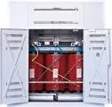
1.7 The enclosure and outgoing busbar
The enclosure provides further safety protection for the transformer, with protection levels such as LP20 and LP23. The enclosure materials include cold-rolled steel plate, stainless steel plate, etc. for users to choose from.
Low voltage outgoing lines use standard busbar outgoing lines, both side and top outgoing lines can be used, and special outgoing methods can also be designed for users.
1.8 Transformer output method
Conventional outlets, standard enclosed busbars, and standard side outlets can be manufactured according to different interface forms, and special outlet methods can also be designed according to user requirements.
| Rated
capacity kV.A |
Voltage combination and tap
range |
Connection
group |
No-load
loss kW |
Load losses at different insulation system temperatures kW | No-load
current % |
Short-circuit impedance % | ||||
| High
voltage |
High voltage
tap range % |
Low
voltage |
130℃ (B)(100℃ ) | 155℃ (F)(120℃ ) | 180℃ (H)(145℃ ) | |||||
| 315 | 6 6.3 6.6 10 10.5 11 |
±4×2.5 | 0.4 | Dyn11 Yyn0 |
0.89 | 3.40 | 3.61 | 3.86 | 1.1 | 4.0 |
| 400 | 1.00 | 4.02 | 4.27 | 4.57 | 1.1 | |||||
| 500 | 1.16 | 4.92 | 5.22 | 5.58 | 1.1 | |||||
| 630 | 1.34 | 5.82 | 6.17 | 6.60 | 1.0 | |||||
| 630 | 1.29 | 6.00 | 6.36 | 6.80 | 1.0 | 6.0 | ||||
| 800 | 1.54 | 7.07 | 7.50 | 8.02 | 1.0 | |||||
| 1000 | 1.78 | 8.28 | 8.78 | 9.39 | 0.85 | |||||
| 1250 | 2.10 | 9.86 | 10.4 | 11.1 | 0.85 | |||||
| 1600 | 2.45 | 11.7 | 12.4 | 13.3 | 0.85 | |||||
| 2000 | 3.08 | 14.3 | 15.2 | 16.2 | 0.7 | |||||
| 2500 | 3.56 | 17.1 | 18.1 | 19.4 | 0.7 | |||||
Note: The load losses listed in the table are the values of different insulation systems under the reference temperature (GB/T1094.11) in parentheses. The load losses of other insulation systems not included in the table need to be converted based on their respective reference temperatures, using the data of the “155 ℃ (F)” insulation system temperature as a reference.