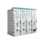
KYN28A-12 Metal Clad Switchgear
KYN28A-12 Metal clad switchgear (hereinafter referred to as switchgear) is suitable for...
From transformers and switchgear to ring main units, substations, circuit breakers and smart components, Jubang provides integrated product support for power distribution projects.
Discover Jubang’s strengths in technology R&D, quality testing and smart manufacturing, supporting reliable electrical equipment and efficient power distribution solutions for global customers.
From technical consultation and OEM/ODM customization to EPC support, smart O&M, delivery documentation and after-sales service, Jubang supports your project at every stage.
Explore Jubang Group’s development history, intelligent manufacturing base, R&D platforms, CNAS-accredited laboratory and global project service capabilities.

Optimized Magnetic Circuit
Energy Saving & Reduced Loss
Low Noise
Strong Overload Capability
Compact Structure
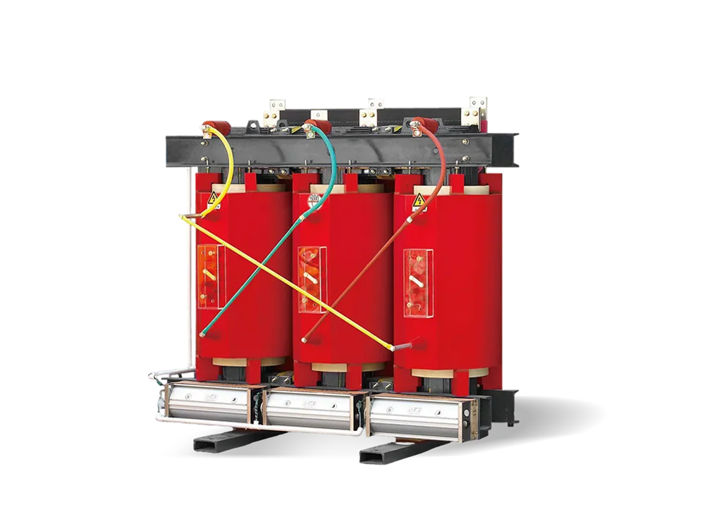
The resin-insulated dry-type transformer is developed by our company based on advanced international technologies. We have independently developed the SC(B)10, SC(B)11, SC(B)12, SC(B)13 and SC(B)14 series.
The transformers adopt epoxy resin vacuum casting technology, featuring flame retardancy, explosion-proof performance, maintenance-free operation, and environmental friendliness. They are compact in size and can be installed directly in load centers.
Through optimized structural design and resin casting technology, the transformer has reduced partial discharge, low noise, and strong heat dissipation capability. Under forced air cooling conditions, it can operate continuously at 140% of rated load.
The transformer is equipped with an intelligent temperature controller, providing functions such as fault alarm, over-temperature alarm, and tripping protection. It can also be connected to computers for remote monitoring and control.
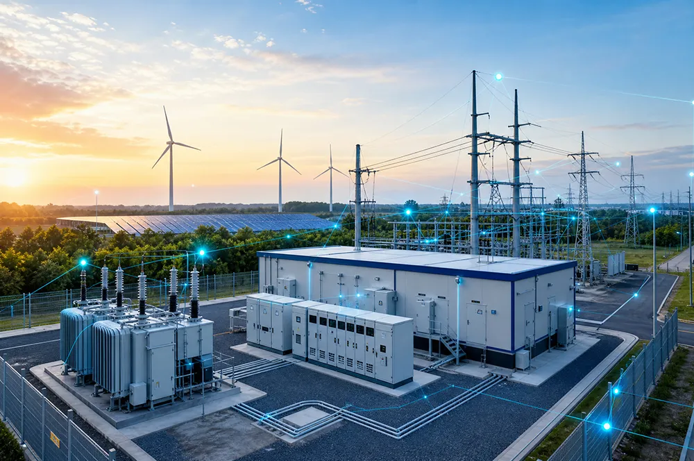
Due to these advantages, the transformer is widely used in urban power distribution systems, including hotels, airports, high-rise buildings, commercial centers, residential areas, as well as demanding environments such as subways, power plants, ships, and offshore drilling platforms.
The transformer core is made of high-quality imported cold-rolled silicon steel sheets with a fully mitered joint structure. The core columns are bound with glass fiber reinforced epoxy bands without adhesives.
The core surface is sealed with insulating resin coating, effectively preventing moisture and corrosion while reducing no-load loss, no-load current, and core noise. Special surface treatment is applied to structural components and fasteners, improving the overall appearance and quality of the product.
The high-voltage winding adopts epoxy resin vacuum pressure casting with quartz filler, which greatly reduces partial discharge and enhances the electrical strength of the winding.
The inner and outer surfaces of the winding are reinforced with glass fiber mesh plates, improving mechanical strength and short-circuit resistance. The winding structure ensures that the coil will not crack during operation.
The low-voltage winding adopts a foil-wound structure, effectively eliminating axial spiral stress during winding and improving current balance.
At the same time, the winding is designed with axial air-cooling channels, enhancing heat dissipation performance. The winding layers use DMD epoxy resin prepreg insulation, forming a solid structure after curing.
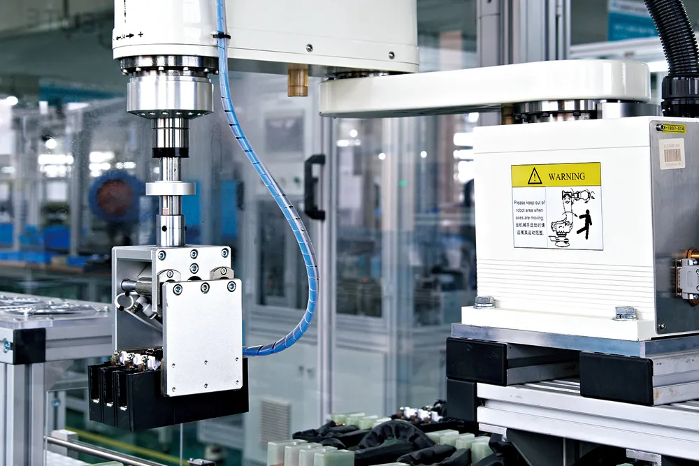
The windings are manufactured using high-precision winding machines, and the low-voltage winding adopts a foil-winding structure.
For transformers with larger capacities, ventilation channels are designed inside the windings. After winding, the coils undergo vacuum drying, followed by vacuum casting and curing strictly according to process requirements. All production processes are carefully monitored and adjusted when necessary.
The precise casting process ensures that the windings are free from bubbles and voids, resulting in high product quality.
The transformer adopts a top-mounted cross-flow cooling fan, featuring low noise, high airflow, and an aesthetically pleasing design. This enhances the overload capability of the transformer.
An intelligent temperature controller is used for temperature monitoring, significantly improving the operational safety and reliability of the transformer.
The protective enclosure provides additional safety protection for the transformer, with protection ratings such as IP20 and IP23 available. The enclosure can be manufactured from cold-rolled steel plate or stainless steel, according to user requirements.
The low-voltage outlet is typically connected through a standard busbar arrangement, and both
top and side cable outlet configurations are available. Customized outlet arrangements can also be designed according to customer requirements.
Different cable outlet configurations can be provided according to various installation and connection requirements, including standard top cable outlet, standard side cable outlet, and other customized outlet arrangements designed according to user requirements.
![]()
GB/T10228 GB/T1094.1 GB/T1094.11 GB/T1094.12 GB/T4208 JB/T10088 GB20052
![]()
![]()
![]()
Technical Data of SC(B)10 Series 6kV/10kV Off-Circuit Tap-Changing Dry-Type Transformers
| Rated Capacity(KVA) | Voltage Combination & Tapping Range | Vector Group | No-Load Loss(kW) | Load Loss(KW) at Different Insulation Thermal Classes |
No-Load Current(%) | Short-Circuit Impedance(%) | ||||
| HV | HV Tapping Range(%) | LV | Class B(130℃/100℃) | Class F(155℃/120℃) | Class H(180℃/145℃) | |||||
| 30 | 6 6.3 6.6 10 10.5 11 |
±2×2.5 ±5 |
0.4 | Dyn11 Yyn0 |
0.19 | 0.670 | 0.710 | 0.760 | 2.0 | 4 |
| 50 | 0.27 | 0.940 | 1.00 | 1.07 | 2.0 | |||||
| 80 | 0.37 | 1.29 | 1.38 | 1.48 | 1.5 | |||||
| 100 | 0.40 | 1.48 | 1.57 | 1.69 | 1.5 | |||||
| 125 | 0.47 | 1.74 | 1.85 | 1.98 | 1.3 | |||||
| 160 | 0.54 | 2.00 | 2.13 | 2.28 | 1.3 | |||||
| 200 | 0.62 | 2.37 | 2.53 | 2.71 | 1.1 | |||||
| 250 | 0.72 | 2.59 | 2.76 | 2.69 | 1.1 | |||||
| 315 | 0.88 | 3.27 | 3.47 | 3.73 | 1.0 | |||||
| 400 | 0.98 | 3.75 | 3.99 | 4.28 | 1.0 | |||||
| 500 | 1.16 | 4.59 | 4.88 | 5.23 | 1.0 | |||||
| 630 | 1.34 | 5.53 | 5.88 | 6.29 | 0.85 | |||||
| 630 | 1.30 | 5.61 | 5.96 | 6.40 | 0.85 | 6 | ||||
| 800 | 1.52 | 6.55 | 6.96 | 7.46 | 0.85 | |||||
| 1000 | 1.77 | 7.65 | 8.13 | 8.76 | 0.85 | |||||
| 1250 | 2.09 | 9.10 | 9.69 | 10.3 | 0.85 | |||||
| 1600 | 2.45 | 11.0 | 11.7 | 12.5 | 0.85 | |||||
| 2000 | 3.05 | 13.6 | 14.4 | 15.5 | 0.7 | |||||
| 2500 | 3.60 | 16.1 | 17.1 | 18.4 | 0.7 | |||||
| 1600 | 2.45 | 12.2 | 12.9 | 13.9 | 0.85 | 8 | ||||
| 2000 | 3.05 | 15.0 | 15.9 | 17.1 | 0.7 | |||||
| 2500 | 3.60 | 17.7 | 18.8 | 20.2 | 0.7 | |||||
Technical Data of SC(B)11 Series 6kV/10kV Off-Circuit Tap-Changing Dry-Type Transformers
| Rated Capacity(KVA) | Voltage Combination & Tapping Range | Vector Group | No-Load Loss(kW) | Load Loss(KW) at Different Insulation Thermal Classes |
No-Load Current(%) | Short-Circuit Impedance(%) | ||||
| HV | HV Tapping Range(%) | LV | Class B(130℃/100℃) | Class F(155℃/120℃) | Class H(180℃/145℃) | |||||
| 30 | 6 6.3 6.6 10 10.5 11 |
±2×2.5 ±5 |
0.4 | Dyn11 Yyn0 |
0.17 | 0.670 | 0.710 | 0.760 | 2.0 | 4 |
| 50 | 0.24 | 0.940 | 1.00 | 1.07 | 2.0 | |||||
| 80 | 0.33 | 1.29 | 1.38 | 1.48 | 1.5 | |||||
| 100 | 0.36 | 1.48 | 1.57 | 1.69 | 1.5 | |||||
| 125 | 0.42 | 1.74 | 1.85 | 1.98 | 1.3 | |||||
| 160 | 0.48 | 2.00 | 2.13 | 2.28 | 1.3 | |||||
| 200 | 0.55 | 2.37 | 2.53 | 2.71 | 1.1 | |||||
| 250 | 0.64 | 2.59 | 2.76 | 2.69 | 1.1 | |||||
| 315 | 0.79 | 3.27 | 3.47 | 3.73 | 1.0 | |||||
| 400 | 0.88 | 3.75 | 3.99 | 4.28 | 1.0 | |||||
| 500 | 1.04 | 4.59 | 4.88 | 5.23 | 1.0 | |||||
| 630 | 1.20 | 5.53 | 5.88 | 6.29 | 0.85 | |||||
| 630 | 1.17 | 5.61 | 5.96 | 6.40 | 0.85 | 6 | ||||
| 800 | 1.36 | 6.55 | 6.96 | 7.46 | 0.85 | |||||
| 1000 | 1.59 | 7.65 | 8.13 | 8.76 | 0.85 | |||||
| 1250 | 1.88 | 9.10 | 9.69 | 10.3 | 0.85 | |||||
| 1600 | 2.20 | 11.0 | 11.7 | 12.5 | 0.85 | |||||
| 2000 | 2.74 | 13.6 | 14.4 | 15.5 | 0.7 | |||||
| 2500 | 3.24 | 16.1 | 17.1 | 18.4 | 0.7 | |||||
| 1600 | 2.20 | 12.2 | 12.9 | 13.9 | 0.85 | 8 | ||||
| 2000 | 2.74 | 15.0 | 15.9 | 17.1 | 0.7 | |||||
| 2500 | 3.24 | 17.7 | 18.8 | 20.2 | 0.7 | |||||
Technical Data of SC(B)12 Series 6kV/10kV Off-Circuit Tap-Changing Dry-Type Transformers
| Rated Capacity(KVA) | Voltage Combination & Tapping Range | Vector Group | No-Load Loss(kW) | Load Loss(KW) at Different Insulation Thermal Classes |
No-Load Current(%) | Short-Circuit Impedance(%) | ||||
| HV | HV Tapping Range(%) | LV | Class B(130℃/100℃) | Class F(155℃/120℃) | Class H(180℃/145℃) | |||||
| 30 | 6 6.3 6.6 10 10.5 11 |
±2×2.5 ±5 |
0.4 | Dyn11 Yyn0 |
0.150 | 0.670 | 0.710 | 0.76 | 2.0 | 4 |
| 50 | 0.215 | 0.940 | 1.00 | 1.07 | 2.0 | |||||
| 80 | 0.295 | 1.29 | 1.38 | 1.48 | 1.5 | |||||
| 100 | 0.320 | 1.48 | 1.57 | 1.69 | 1.5 | |||||
| 125 | 0.375 | 1.74 | 1.85 | 1.98 | 1.3 | |||||
| 160 | 0.430 | 2.00 | 2.13 | 2.28 | 1.3 | |||||
| 200 | 0.495 | 2.37 | 2.53 | 2.71 | 1.1 | |||||
| 250 | 0.575 | 2.59 | 2.76 | 2.69 | 0.9 | |||||
| 315 | 0.705 | 3.27 | 3.47 | 3.73 | 0.8 | |||||
| 400 | 0.785 | 3.75 | 3.99 | 4.28 | 0.8 | |||||
| 500 | 0.930 | 4.59 | 4.88 | 5.23 | 0.8 | |||||
| 630 | 1.07 | 5.53 | 5.88 | 6.29 | 0.7 | |||||
| 630 | 1.04 | 5.61 | 5.96 | 6.40 | 0.7 | 6 | ||||
| 800 | 1.21 | 6.55 | 6.96 | 7.46 | 0.7 | |||||
| 1000 | 1.41 | 7.65 | 8.13 | 8.76 | 0.7 | |||||
| 1250 | 1.67 | 9.10 | 9.69 | 10.3 | 0.7 | |||||
| 1600 | 1.96 | 11.0 | 11.7 | 12.5 | 0.7 | |||||
| 2000 | 2.44 | 13.6 | 14.4 | 15.5 | 0.6 | |||||
| 2500 | 2.88 | 16.1 | 17.1 | 18.4 | 0.6 | |||||
| 1600 | 1.96 | 12.2 | 12.9 | 13.9 | 0.7 | 8 | ||||
| 2000 | 2.44 | 15.0 | 15.9 | 17.1 | 0.6 | |||||
| 2500 | 2.88 | 17.7 | 18.8 | 20.2 | 0.6 | |||||
Technical Data – SC(B)13 Series 6kV/10kV Dry-Type Transformer
| Rated Capacity(KVA) | Voltage Combination & Tapping Range | Vector Group | No-Load Loss(kW) | Load Loss(KW) at Different Insulation Thermal Classes |
No-Load Current(%) | Short-Circuit Impedance(%) | ||||
| HV | HV Tapping Range(%) | LV | Class B(130℃/100℃) | Class F(155℃/120℃) | Class H(180℃/145℃) | |||||
| 30 | 6 6.3 6.6 10 10.5 11 |
±2×2.5 ±5 |
0.4 | Dyn11 Yyn0 |
0.135 | 0.605 | 0.640 | 0.685 | 2.0 | 4 |
| 50 | 0.195 | 0.845 | 0.900 | 0.965 | 2.0 | |||||
| 80 | 0.265 | 1.16 | 1.24 | 1.33 | 1.5 | |||||
| 100 | 0.290 | 1.33 | 1.41 | 1.52 | 1.5 | |||||
| 125 | 0.340 | 1.56 | 1.66 | 1.78 | 1.3 | |||||
| 160 | 0.385 | 1.80 | 1.91 | 2.05 | 1.3 | |||||
| 200 | 0.445 | 2.13 | 2.27 | 2.44 | 1.1 | |||||
| 250 | 0.515 | 2.33 | 2.48 | 2.66 | 0.9 | |||||
| 315 | 0.635 | 2.94 | 3.12 | 3.35 | 0.8 | |||||
| 400 | 0.705 | 3.37 | 3.59 | 3.85 | 0.8 | |||||
| 500 | 0.835 | 4.13 | 4.39 | 4.70 | 0.8 | |||||
| 630 | 0.965 | 4.97 | 5.29 | 5.66 | 0.7 | |||||
| 630 | 0.935 | 5.05 | 5.36 | 5.76 | 0.7 | 6 | ||||
| 800 | 1.09 | 5.89 | 6.26 | 6.71 | 0.7 | |||||
| 1000 | 1.27 | 6.88 | 7.31 | 7.88 | 0.7 | |||||
| 1250 | 1.50 | 8.19 | 8.72 | 9.33 | 0.7 | |||||
| 1600 | 1.76 | 9.94 | 10.5 | 11.3 | 0.7 | |||||
| 2000 | 2.19 | 12.2 | 13.0 | 14.0 | 0.6 | |||||
| 2500 | 2.59 | 14.5 | 15.4 | 16.6 | 0.6 | |||||
| 1600 | 1.76 | 11.0 | 11.6 | 12.5 | 0.7 | 8 | ||||
| 2000 | 2.19 | 13.5 | 14.3 | 15.4 | 0.6 | |||||
| 2500 | 2.59 | 15.9 | 17.0 | 18.2 | 0.6 | |||||
Note:
Load loss values are given for different insulation systems at the reference temperatures specified
in GB/T1094.11. Values for other insulation systems can be calculated from the Class F (155℃) reference data.
Technical Data – SC(B)12 Series Grade 3 Energy-Efficient 6kV/10kV Dry-Type Transformers
| Rated Capacity(KVA) | Voltage Combination & Tapping Range | Vector Group | No-Load Loss(kW) | Load Loss(KW) at Different Insulation Thermal Classes |
No-Load Current(%) | Short-Circuit Impedance(%) | ||||
| HV | HV Tapping Range(%) | LV | Class B(130℃/100℃) | Class F(155℃/120℃) | Class H(180℃/145℃) | |||||
| 30 | 6 6.3 6.6 10 10.5 11 |
±2×2.5 ±5 |
0.4 | Dyn11 Yyn0 |
0.150 | 0.670 | 0.710 | 0.760 | 2.0 | 4 |
| 50 | 0.215 | 0.940 | 1.000 | 1.070 | 2.0 | |||||
| 80 | 0.295 | 1.290 | 1.380 | 1.480 | 1.5 | |||||
| 100 | 0.320 | 1.480 | 1.570 | 1.690 | 1.5 | |||||
| 125 | 0.375 | 1.740 | 1.850 | 1.980 | 1.3 | |||||
| 160 | 0.430 | 2.000 | 2.130 | 2.280 | 1.3 | |||||
| 200 | 0.495 | 2.370 | 2.530 | 2.710 | 1.1 | |||||
| 250 | 0.575 | 2.590 | 2.760 | 2.960 | 0.9 | |||||
| 315 | 0.705 | 3.270 | 3.470 | 3.730 | 0.8 | |||||
| 400 | 0.785 | 3.750 | 3.990 | 4.280 | 0.8 | |||||
| 500 | 0.930 | 4.590 | 4.880 | 5.230 | 0.8 | |||||
| 630 | 1.070 | 5.530 | 5.880 | 6.290 | 0.7 | |||||
| 630 | 1.040 | 5.610 | 5.960 | 6.400 | 0.7 | 6 | ||||
| 800 | 1.215 | 6.550 | 6.960 | 7.460 | 0.7 | |||||
| 1000 | 1.415 | 7.650 | 8.130 | 8.760 | 0.7 | |||||
| 1250 | 1.670 | 9.100 | 9.690 | 10.370 | 0.7 | |||||
| 1600 | 1.960 | 11.050 | 11.730 | 12.580 | 0.7 | |||||
| 2000 | 2.440 | 13.600 | 14.450 | 15.560 | 0.6 | |||||
| 2500 | 2.880 | 16.150 | 17.170 | 18.450 | 0.6 | |||||
Notes:
① Load loss values are given for different insulation systems at the reference temperatures specified in GB/T1094.11. Values for other insulation systems may be calculated from the Class F (155℃) reference data.
② No-load loss values comply with GB20052-2020 Grade 3 energy efficiency requirements.
Technical Data – SC(B)14 Series Grade 2 Energy-Efficient 6kV/10kV Dry-Type Transformers
| Rated Capacity(KVA) | Voltage Combination & Tapping Range | Vector Group | No-Load Loss(kW) | Load Loss(KW) at Different Insulation Thermal Classes |
No-Load Current(%) | Short-Circuit Impedance(%) | ||||
| HV | HV Tapping Range(%) | LV | Class B(130℃/100℃) | Class F(155℃/120℃) | Class H(180℃/145℃) | |||||
| 30 | 6 6.3 6.6 10 10.5 11 |
±2×2.5 ±5 |
0.4 | Dyn11 Yyn0 |
0.13 | 0.605 | 0.640 | 0.685 | 2.0 | 4 |
| 50 | 0.185 | 0.845 | 0.900 | 0.965 | 2.0 | |||||
| 80 | 0.250 | 1.160 | 1.240 | 1.330 | 1.5 | |||||
| 100 | 0.270 | 1.330 | 1.415 | 1.520 | 1.5 | |||||
| 125 | 0.320 | 1.565 | 1.665 | 1.780 | 1.3 | |||||
| 160 | 0.365 | 1.800 | 1.915 | 2.050 | 1.3 | |||||
| 200 | 0.420 | 2.135 | 2.275 | 2.440 | 1.1 | |||||
| 250 | 0.490 | 2.330 | 2.485 | 2.665 | 0.9 | |||||
| 315 | 0.600 | 2.945 | 3.125 | 3.355 | 0.8 | |||||
| 400 | 0.665 | 3.375 | 3.590 | 3.850 | 0.8 | |||||
| 500 | 0.790 | 4.130 | 4.390 | 4.705 | 0.8 | |||||
| 630 | 0.910 | 4.975 | 5.290 | 5.660 | 0.7 | |||||
| 630 | 0.885 | 5.050 | 5.365 | 5.760 | 0.7 | 6 | ||||
| 800 | 1.035 | 5.895 | 6.265 | 6.715 | 0.7 | |||||
| 1000 | 1.205 | 6.885 | 7.315 | 7.885 | 0.7 | |||||
| 1250 | 1.420 | 8.190 | 8.720 | 9.335 | 0.7 | |||||
| 1600 | 1.665 | 9.945 | 10.555 | 11.320 | 0.7 | |||||
| 2000 | 2.075 | 12.240 | 13.005 | 14.005 | 0.6 | |||||
| 2500 | 2.450 | 14.535 | 15.445 | 16.605 | 0.6 | |||||
Notes:
① Load loss values are given for different insulation systems at the reference temperatures specified in GB/T1094.11. Values for other insulation systems may be calculated from the Class F (155℃) reference data.
② No-load loss values comply with GB20052-2020 Grade 2 energy efficiency requirements.
Technical Data – SC(B)18 Series Grade 1 Energy-Efficient 6kV/10kV Dry-Type Transformers
| Rated Capacity(KVA) | Voltage Combination & Tapping Range | Vector Group | No-Load Loss(kW) | Load Loss(KW) at Different Insulation Thermal Classes |
No-Load Current(%) | Short-Circuit Impedance(%) | ||||
| HV | HV Tapping Range(%) | LV | Class B(130℃/100℃) | Class F(155℃/120℃) | Class H(180℃/145℃) | |||||
| 30 | 6 6.3 6.6 10 10.5 11 |
±2×2.5 ±5 |
0.4 | Dyn11 Yyn0 |
0.105 | 0.605 | 0.640 | 0.685 | 2.0 | 4 |
| 50 | 0.155 | 0.845 | 0.900 | 0.965 | 2.0 | |||||
| 80 | 0.210 | 1.160 | 1.240 | 1.330 | 1.5 | |||||
| 100 | 0.230 | 1.330 | 1.415 | 1.520 | 1.5 | |||||
| 125 | 0.270 | 1.565 | 1.665 | 1.780 | 1.3 | |||||
| 160 | 0.310 | 1.800 | 1.915 | 2.050 | 1.3 | |||||
| 200 | 0.360 | 2.135 | 2.275 | 2.440 | 1.1 | |||||
| 250 | 0.415 | 2.330 | 2.485 | 2.665 | 0.9 | |||||
| 315 | 0.510 | 2.945 | 3.125 | 3.355 | 0.8 | |||||
| 400 | 0.570 | 3.375 | 3.590 | 3.850 | 0.8 | |||||
| 500 | 0.670 | 4.130 | 4.390 | 4.705 | 0.8 | |||||
| 630 | 0.775 | 4.975 | 5.290 | 5.660 | 0.7 | |||||
| 630 | 0.750 | 5.050 | 5.365 | 5.760 | 0.7 | 6 | ||||
| 800 | 0.875 | 5.895 | 6.265 | 6.715 | 0.7 | |||||
| 1000 | 1.020 | 6.885 | 7.315 | 7.885 | 0.7 | |||||
| 1250 | 1.205 | 8.190 | 8.720 | 9.335 | 0.7 | |||||
| 1600 | 1.415 | 9.945 | 10.555 | 11.320 | 0.7 | |||||
| 2000 | 1.760 | 12.240 | 13.005 | 14.005 | 0.6 | |||||
| 2500 | 2.080 | 14.535 | 15.445 | 16.605 | 0.6 | |||||
Notes:
① Load loss values are given for different insulation systems at the reference temperatures specified in GB/T1094.11. Values for other insulation systems may be calculated from the Class F (155℃) reference data.
② No-load loss values comply with GB20052-2020 Grade 1 energy efficiency requirements.
Overall Dimension Drawings of SC(B)10/SC(B)11 Series Off-Circuit Tap-Changing Dry-Type Transformers
![]()
| Rated Capacity(kVA) | Overall Dimensions(mm) | Overall Dimensions with Enclosure(mm) | ||||||||
| L1 | W1 | H1 | D1 | A1 | L2 | W2 | H2 | D2 | A2 | |
| 10 | 600 | 400 | 520 | 350 | 400 | 400 | 900 | 1150 | 400 | 800 |
| 20 | 600 | 400 | 520 | 350 | 400 | 400 | 900 | 1150 | 400 | 800 |
| 30 | 600 | 400 | 620 | 400 | 350 | 350 | 950 | 1200 | 400 | 850 |
| 50 | 630 | 450 | 660 | 400 | 350 | 350 | 950 | 1200 | 400 | 850 |
| 63 | 780 | 500 | 765 | 400 | 400 | 400 | 980 | 1300 | 400 | 880 |
| 80 | 780 | 500 | 765 | 400 | 400 | 400 | 1000 | 1300 | 400 | 900 |
| 100 | 890 | 650 | 830 | 550 | 550 | 550 | 1000 | 1300 | 550 | 900 |
| 125 | 910 | 650 | 850 | 550 | 550 | 550 | 1000 | 1400 | 550 | 900 |
| 160 | 950 | 750 | 965 | 550 | 660 | 660 | 1150 | 1450 | 550 | 1050 |
| 200 | 1000 | 750 | 1120 | 550 | 660 | 660 | 1150 | 1500 | 550 | 1050 |
| 250 | 1040 | 750 | 1155 | 660 | 660 | 660 | 1200 | 1550 | 660 | 1100 |
| 315 | 1080 | 750 | 1220 | 660 | 660 | 660 | 1200 | 1650 | 660 | 1100 |
| 400 | 1105 | 750 | 1225 | 660 | 660 | 660 | 1250 | 1800 | 660 | 1150 |
| 500 | 1150 | 900 | 1395 | 660 | 820 | 820 | 1250 | 1800 | 660 | 1150 |
| 630 | 1340 | 900 | 1330 | 820 | 820 | 820 | 1300 | 1700 | 820 | 1200 |
| 800 | 1400 | 900 | 1470 | 820 | 820 | 820 | 1350 | 1850 | 820 | 1250 |
| 1000 | 1460 | 900 | 1475 | 820 | 820 | 820 | 1400 | 1900 | 820 | 1300 |
| 1250 | 1485 | 900 | 1605 | 820 | 820 | 820 | 1400 | 1950 | 820 | 1300 |
| 1600 | 1580 | 1050 | 1680 | 950 | 950 | 950 | 1450 | 2050 | 950 | 1350 |
| 2000 | 1690 | 1050 | 1840 | 950 | 950 | 950 | 1550 | 2150 | 950 | 1450 |
| 2500 | 1765 | 1050 | 1885 | 1070 | 950 | 950 | 1600 | 2200 | 1070 | 1500 |
| 3150 | 1950 | 1170 | 1900 | 1070 | 1070 | 1070 | 1600 | 2250 | 1070 | 1500 |
| 4000 | 2030 | 1170 | 2000 | 1070 | 1070 | 1070 | 1600 | 2300 | 1070 | 1500 |
Notes:
① Dimensions are for reference only and may change due to product improvements. Custom dimensions are available upon request.
② For transformers ≤200 kVA, the enclosure is optional and not standard.
Outline Dimension Drawings of SC(B)12-SC(B)18 Series Dry-Type Transformers
![]()
| Rated Capacity(kVA) | Overall Dimensions(mm) | Overall Dimensions with Enclosure(mm) | ||||||||
| L1 | W1 | H1 | D1 | A1 | L2 | W2 | H2 | D2 | A2 | |
| 30 | 600 | 400 | 620 | 400 | 350 | 1050 | 950 | 1200 | 400 | 850 |
| 50 | 630 | 450 | 660 | 400 | 350 | 1050 | 950 | 1200 | 400 | 850 |
| 63 | 820 | 500 | 730 | 400 | 400 | 1050 | 980 | 1300 | 400 | 880 |
| 80 | 820 | 500 | 730 | 400 | 400 | 1050 | 1000 | 1300 | 400 | 900 |
| 100 | 840 | 650 | 770 | 550 | 550 | 1200 | 1000 | 1300 | 550 | 900 |
| 125 | 860 | 650 | 800 | 550 | 550 | 1200 | 1000 | 1400 | 550 | 900 |
| 160 | 900 | 750 | 870 | 550 | 660 | 1250 | 1150 | 1450 | 550 | 1050 |
| 200 | 940 | 750 | 950 | 550 | 660 | 1300 | 1150 | 1500 | 550 | 1050 |
| 250 | 1000 | 750 | 990 | 660 | 660 | 1400 | 1200 | 1550 | 660 | 1100 |
| 315 | 1040 | 750 | 1020 | 660 | 660 | 1400 | 1200 | 1650 | 660 | 1100 |
| 400 | 1080 | 750 | 1040 | 660 | 660 | 1500 | 1250 | 1800 | 660 | 1150 |
| 500 | 1130 | 900 | 1130 | 660 | 820 | 1550 | 1250 | 1800 | 660 | 1150 |
| 630 | 1370 | 900 | 1050 | 820 | 820 | 1700 | 1300 | 1700 | 820 | 1200 |
| 800 | 1420 | 900 | 1110 | 820 | 820 | 1750 | 1350 | 1850 | 820 | 1250 |
| 1000 | 1450 | 900 | 1200 | 820 | 820 | 1850 | 1400 | 1900 | 820 | 1300 |
| 1250 | 1500 | 900 | 1280 | 820 | 820 | 1850 | 1400 | 1950 | 820 | 1300 |
| 1600 | 1550 | 1050 | 1400 | 950 | 950 | 2000 | 1450 | 2050 | 950 | 1350 |
| 2000 | 1640 | 1050 | 1530 | 950 | 950 | 2050 | 1550 | 2150 | 950 | 1450 |
| 2500 | 1720 | 1050 | 1620 | 1070 | 950 | 2150 | 1600 | 2200 | 1070 | 1500 |
Notes:
① Dimensions are for reference only and may change due to product improvements. Custom dimensions are available upon request.
② For transformers ≤200 kVA, cooling fans are not supplied as standard.


