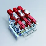
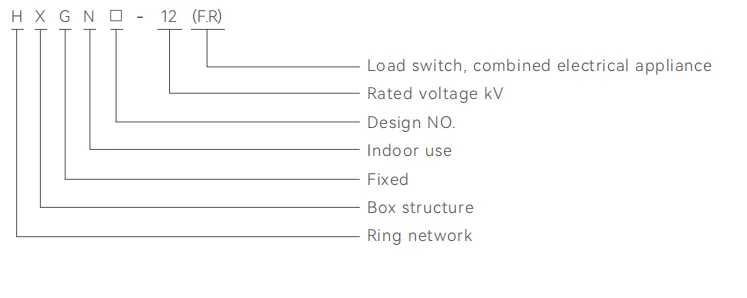
FZ (R)N25-12D-T Series indoor high-voltage AC compressed air load switch fuse combination device
• It is currently the most advanced medium voltage vacuum load switch...
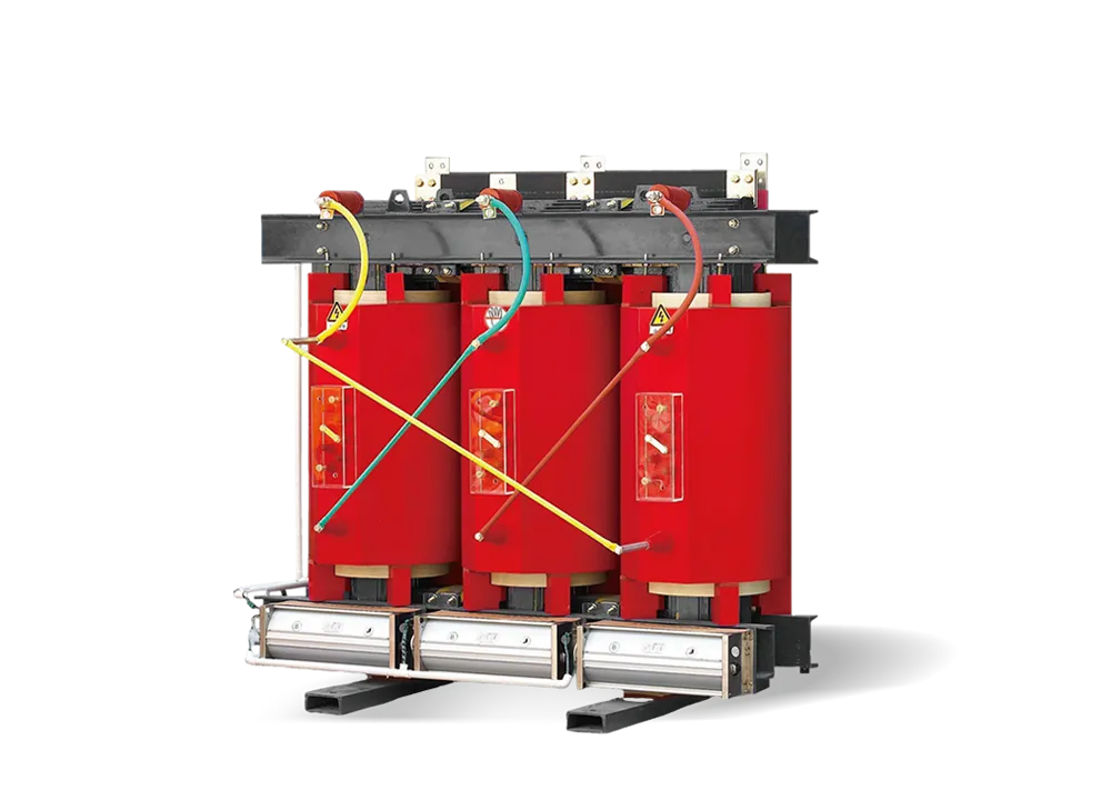
From transformers and switchgear to ring main units, substations, circuit breakers and smart components, Jubang provides integrated product support for power distribution projects.
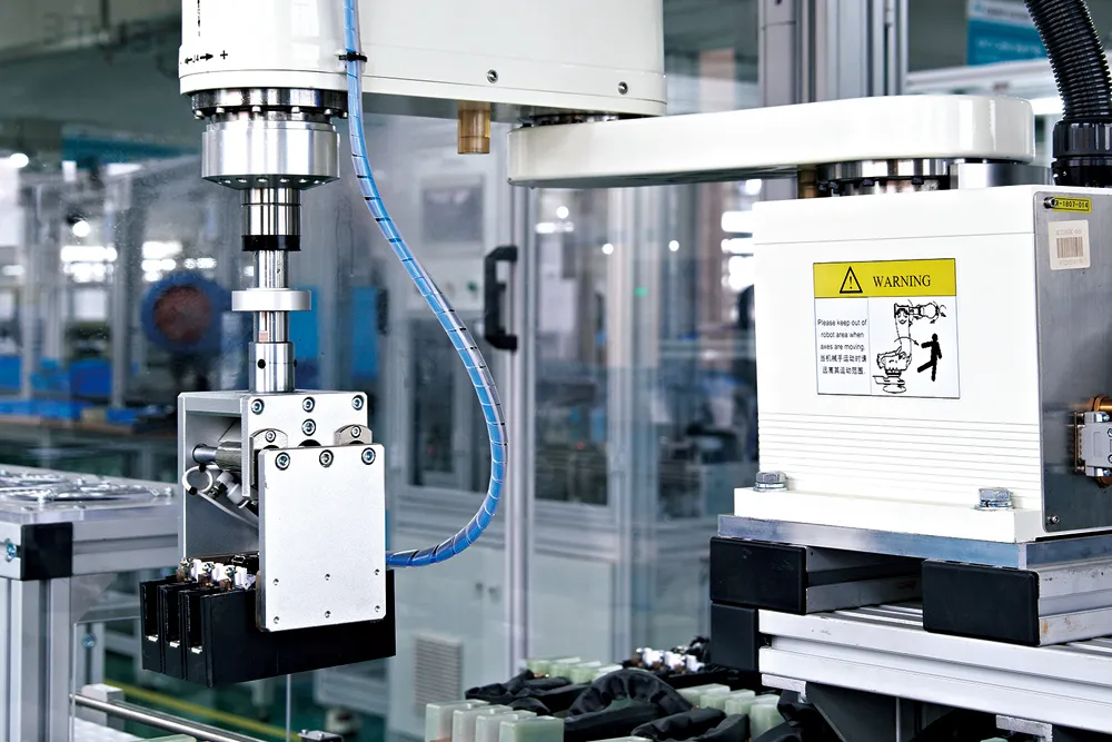
Discover Jubang’s strengths in technology R&D, quality testing and smart manufacturing, supporting reliable electrical equipment and efficient power distribution solutions for global customers.
From technical consultation and OEM/ODM customization to EPC support, smart O&M, delivery documentation and after-sales service, Jubang supports your project at every stage.
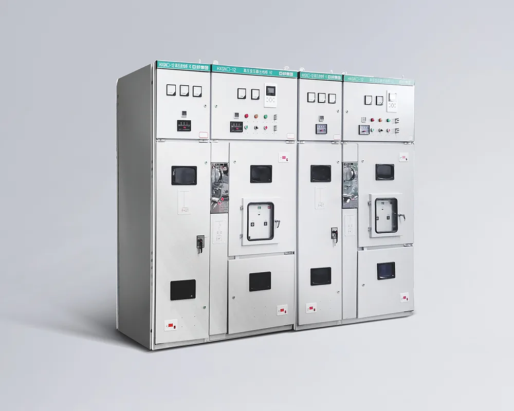
HXGN □ -12 Fixed type metal ring main switchgear (hereinafter referred to as ring main unit) is a new type of high- voltage switchgear produced for the renovation and construction of urban power grids. In the power supply system, the ring main unit is used for breaking load current and making short-circuit current. It is suitable for AC 12kV, 50Hz distribution network systems, and is widely used in urban power grid construction and renovation projects, industrial and mining enterprises, high-rise buildings, and public facilities.
As a ring main power supply unit and terminal equipment, it plays a role in energy distribution, control, and protection of electrical equipment. It can also be installed in box substations. This ring main unit is equipped with a compressed air load switch and a vacuum load switch. The operating mechanism is a spring operated mechanism, which can be operated manually or electrically. Alternatively, it can be equipped with isolation switches and VS1 fixed circuit breakers. This ring main unit has strong integrity, small size, no fire and explosion hazards, and reliable “five prevention” functions.
The ring main unit is equipped with FZRN25-12D switch, FKRN12A-12D switch, GN30-12 switch, and VS1 fixed circuit breaker.
The load switch, isolation switch, VS1 circuit breaker, and cabinet door have complete and reliable mechanical linkAge and interlocking devices, which can effectively prevent misoperation and ensure safe maintenance.
The switch can be manually and electrically operated.
The cabinet door and instrument door of measurement cabinet are equipped with lead sealing pins.
The fuse combination electrical cabinet and fuse tube are equipped with striker pins. In the case of a short circuit, the striker impacts the tripping mechanism, achieving fast switching and effectively protecting electrical equipment; The ring main unit adopts front operation and reliable wall installation.
Power transmission operation: Only when the cabinet door is closed and locked, and the earthing switch is operated to the “open” position, that can the load switch be operated to the closed position.
Power outage operation: The earthing switch can only be closed when the load switch is in the opening position, and the cabinet door can only be opened when the earthing switch is in the closing position.
The isolation knife is reliably interlocked with the circuit breaker and is interlocked with the door, fully meeting the five prevention requirements.
Altitude: ≤ 1000m;
Environment temperature: The upper limit of the ambient air temperature is+40℃ , and the lower limit is -15℃ ;
Relative humidity: The daily average value shall not exceed 95%, and the monthly average value shall not exceed 90%;
Installation site: A place without conductive dust, corrosive gases, and water vapor; Places without fire and explosion hazards; Places without frequent severe vibration.
Note: When the normal usage conditions mentioned above cannot meet the usage requirements, the user shall negotiate with the manufacturer.
| NO. | Item | Unit | Technical parameter | |
| 1 | Rated voltage | kV | 12 | |
| 2 | Rated current | Load switch cabinet | A | 630 |
| Combined electrical cabinet | 125 | |||
| 3 | Rated short-circuit making current (peak value) | KA | 50 | |
| 4 | Rated short-circuit breaking current (combined electrical cabinet) | KA | 31.5 | |
| 5 | Rated Active load breaking current | A | 630 | |
| 6 | 4S thermal stability current | KA | 20 | |
| 7 | Rated dynamic stable current (peak value) | KA | 50 | |
| 8 | 1min power frequency withstand voltage | kV | 42 (Disconnect port, 48) | |
| 9 | Lightning impulse withstand voltage | kV | 75 (Disconnect port, 85) | |
| 10 | Mechanical life | Times | 5000 | |
| 11 | Rated transfer current (combined electrical appliance) | A | 1700 | |
| 12 | Operation mode | Manual or electric | ||
| 13 | Protection level | IP3X | ||
| Scheme No. | 01 | 02 | 03 | 04 | 05 | 06 | ||||||||||||||||||||||||||||||||||
| Circuit name | Cable Incoming and outgoing lines | Cable Incoming and outgoing lines | Cable Incoming and outgoing lines | Cable Incoming and outgoing lines | Cable Incoming and outgoing lines | Cable outgoing | ||||||||||||||||||||||||||||||||||
|
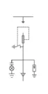
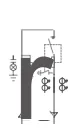
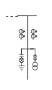
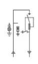
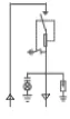
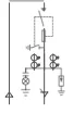
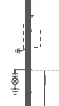
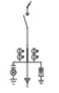
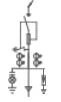
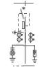
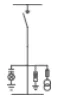
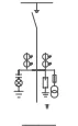
Primary wiring scheme |
|
|
|
|
|
|
||||||||||||||||||||||||||||||||||
|
Cab inet size |
W* D*H (mm) |
W | 450~1000 | 650~1000 | 650~1000 | 650~1000 | 800~1000 | 650~1000 | ||||||||||||||||||||||||||||||||
| D | 900 | 950 | 1000 | 900 | 950 | 1000 | 900 | 950 | 1000 | 900 | 950 | 1000 | 900 | 950 | 1000 | 900 | 950 | 1000 | ||||||||||||||||||||||
| H | 1900 | 2000 | 2200 | 1900 | 2000 | 2200 | 1900 | 2000 | 2200 | 1900 | 2000 | 2200 | 1900 | 2000 | 2200 | 1900 | 2000 | 2200 | ||||||||||||||||||||||
| Dimension remarks | Width size 50 gears | |||||||||||||||||||||||||||||||||||||||
|
Main electrical components |
Vacuum load switch | Optional | FZN25-12/ T630-20 | FZN25-12/ T630-20 | FZN25-12/ T630-20 | FZN25-12/
T630-20 |
FZRN25-12D/ T200- 31.5 | |||||||||||||||||||||||||||||||||
| Compressor
load switch |
FKN12A-12/ T630- 20 | FKN12A-12/ T630- 20 | FKN12A-12/ T630- 20 | FKN12A-12/ T630- 20 | FKRN12A-12D/ T125-31.5 | |||||||||||||||||||||||||||||||||||
| Current transformer | LZZBJ9-10 | LZZBJ9-10 | LZZBJ9-10 | |||||||||||||||||||||||||||||||||||||
| Voltage transformer | JDZ(X)10-10 | JDZ(X)10-10 | ||||||||||||||||||||||||||||||||||||||
| High voltage fuse | XRNP-12/0.5A | XRNP-12/0.5A | XRNT-12 | |||||||||||||||||||||||||||||||||||||
| Lightning arrester | HY5WS-17/50 | HY5WS-17/50 | HY5WS-17/50 | HY5WS-17/50 | HY5WS-17/50 | HY5WS-17/50 | ||||||||||||||||||||||||||||||||||
| Charged display | DXN-10Q/T(Q) | DXN-10Q/T(Q) | DXN-10Q/T(Q) | DXN-10Q/T(Q) | DXN-10Q/T(Q) | DXN-10Q/T(Q) | ||||||||||||||||||||||||||||||||||
| Remarks | When installing the load switch, the minimum cabinet width is 950mm | |||||||||||||||||||||||||||||||||||||||
| Scheme No. | 07 | 08 | 09 | 10 | 11 | 12 | ||||||||||||||
| Circuit name | Cable Incoming and outgoing lines | Cable Incoming and outgoing lines | Cable Incoming and outgoing lines | Cable Incoming and outgoing lines | Cable Incoming and outgoing lines | Cable outgoing | ||||||||||||||
|
Primary wiring scheme |
|
|
|
|
|
|
||||||||||||||
|
Cabinet size |
W* D*H (mm) |
W | 650~1000 | 650~1000 | 650~1000 | 650~1000 | 800~1000 | 650~1000 | ||||||||||||
| D | 900 | 950 | 1000 | 900 | 950 | 1000 | 900 | 950 | 1000 | 900 | 950 | 1000 | 900 | 950 | 1000 | 900 | 950 | 1000 | ||
| H | 1900 | 2000 | 2200 | 1900 | 2000 | 2200 | 1900 | 2000 | 2200 | 1900 | 2000 | 2200 | 1900 | 2000 | 2200 | 1900 | 2000 | 2200 | ||
| Dimension remarks | Width size 50 gears | 1.When the incoming cable is directly pulled to the bus bar compartment for overlap, the cabinet width is 850; | Width size 50 gears | |||||||||||||||||
| 2. When the incoming cable is overlapped in the cable room, the minimum size of the cabinet width is 650. | ||||||||||||||||||||
|
Main electrical components |
Vacuum load switch | Optional | FZRN25-12D/ T200- 31.5 | FZRN25-12D/ T200- 31.5 | FZRN25-12D/ T200- 31.5 | FZRN25-12D/ T200- 31.5 | FZRN25-12D/ T200- 31.5 | |||||||||||||
| Compressor
load switch |
FKRN12A-12D/ T125-31.5 | FKRN12A-12D/ T125-31.5 | FKRN12A-12D/ T125-31.5 | FKRN12A-12D/ T125-31.5 | FKRN12A-12D/ T125-31.5 | |||||||||||||||
|
|
Current transformer | LZZBJ9-10 | LZZBJ9-10 | LZZBJ9-10 | ||||||||||||||||
|
|
Voltage transformer | JDZ(X)10-10 | ||||||||||||||||||
|
|
High voltage fuse | |||||||||||||||||||
|
|
Lightning arrester | XRNT-12 | XRNT-12 | XRNT-12 | XRNT-12 | XRNT-12 | XRNP-12/0.5A | |||||||||||||
| Charged display | DXN-10Q/T(Q) | DXN-10Q/T(Q) | DXN-10Q/T(Q) | DXN-10Q/T(Q) | DXN-10Q/T(Q) | DXN-10Q/T(Q) | ||||||||||||||
| Remarks | When installing the load switch, the minimum cabinet width is 950mm | |||||||||||||||||||
| Scheme No. | 13 | 14 | 15 | 16 | 17 | 18 | |||||||||||||||||
| Circuit name | Metering | Metering | Overhead cable incoming line | Overhead cable incoming line | Overhead cable incoming line | Overhead cable incoming line | |||||||||||||||||
| Primary wiring scheme | 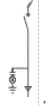 |
 |
 |
 |
|||||||||||||||||||
|
Cabinet size |
W* D*H (mm) | W | 650~1000 | 650~1000 | 650~1000 | 650~1000 | 800~1000 | 650~1000 | |||||||||||||||
| D | 900 | 950 | 1000 | 900 | 950 | 1000 | 900 | 950 | 1000 | 900 | 950 | 1000 | 900 | 950 | 1000 | 900 | 950 | 1000 | |||||
| H | 1900 | 2000 | 2200 | 1900 | 2000 | 2200 | 1900 | 2000 | 2200 | 1900 | 2000 | 2200 | 1900 | 2000 | 2200 | 1900 | 2000 | 2200 | |||||
| Dimension remarks | Width size 50 gears | ||||||||||||||||||||||
|
Main electrical components |
Vacuum load switch | Optional | FZN25-12/ T630-20 | FZRN25-12D/ T200-31.5 | FZN25-12/ T630-20 | FZRN25-12D/ T200-31.5 | |||||||||||||||||
| Compressor
load switch |
FKN12A-12/ T630-20 | FKRN12A-12D/ T125-31.5 | FKN12A-12/ T630-20 | FKRN12A-12D/ T125-31.5 | |||||||||||||||||||
| Current transformer | LZZBJ9-10 | LZZBJ9-10 | LZZBJ9-10 | LZZBJ9-10 | |||||||||||||||||||
| Voltage transformer | JDZ(X)10-10 | JDZ(X)10-10 | |||||||||||||||||||||
| High voltage fuse | XRNP-12/0.5A | XRNP-12/0.5A | XRNT-12 | XRNT-12 | |||||||||||||||||||
| Lightning arrester | HY5WS-17/50 | HY5WS-17/50 | HY5WS-17/50 | HY5WS-17/50 | |||||||||||||||||||
| Charged display | DXN-10Q/T(Q) | DXN-10Q/T(Q) | DXN-10Q/T(Q) | DXN-10Q/T(Q) | DXN-10Q/T(Q) | DXN-10Q/T(Q) | |||||||||||||||||
| Remarks | Note : When installing the load switch, the minimum cabinet width is 950mm | ||||||||||||||||||||||
| Scheme No. | 19 | 20 | 21 | 22 | 23 | 24 | ||||||||||||||||
| Circuit name | liaison | liaison | liaison | liaison | liaison | liaison | ||||||||||||||||
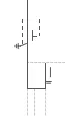
| Primary wiring scheme | 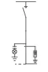 |
 |
|
 |
 |
 |
||||||||||||||||
|
Cabinet size |
W* D*H (mm) | W | 650~1000 | 650~1000 | 650~1000 | 650~1000 | 800~1000 | 650~1000 | ||||||||||||||
| D | 900 | 950 | 1000 | 900 | 950 | 1000 | 900 | 950 | 1000 | 900 | 950 | 1000 | 900 | 950 | 1000 | 900 | 950 | 1000 | ||||
| H | 1900 | 2000 | 2200 | 1900 | 2000 | 2200 | 1900 | 2000 | 2200 | 1900 | 2000 | 2200 | 1900 | 2000 | 2200 | 1900 | 2000 | 2200 | ||||
| ze | Dimension remarks | Width size 50 gears | ||||||||||||||||||||
|
Main electrical components ctric a l co mp one nts |
Vacuum load switch | Optional | FZN25-12/ T630-20 | FZRN25-12D/ T200-31.5 | FZN25-12/ T630-20 | FZRN25-12D/ T200-31.5 | FZN25-12/ T630-20 | FZN25-12/ T630-20 | ||||||||||||||
| Compressor
load switch |
FKN12A-12/ T630-20 | FKRN12A-12D/ T125-31.5 | FKN12A-12/ T630-20 | FKRN12A-12D/ T125-31.5 | FKN12A-12/ T630-20 | FKN12A-12/ T630-20 | ||||||||||||||||
| Current transformer | LZZBJ9-10 | LZZBJ9-10 | LZZBJ9-10 | |||||||||||||||||||
| Voltage transformer | JDZ(X)10-10 | JDZ(X)10-10 | ||||||||||||||||||||
| High voltage fuse | XRNP-12/0.5A | XRNP-12/0.5A | ||||||||||||||||||||
| Lightning arrester | HY5WS-17/50 | HY5WS-17/50 | HY5WS-17/50 | HY5WS-17/50 | HY5WS-17/50 | HY5WS-17/50 | ||||||||||||||||
| Charged display | DXN-10Q/T(Q) | DXN-10Q/T(Q) | DXN-10Q/T(Q) | DXN-10Q/T(Q) | DXN-10Q/T(Q) | DXN-10Q/T(Q) | ||||||||||||||||
| Remarks | When installing the load switch, the minimum cabinet width is 950mm | |||||||||||||||||||||