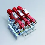
FZ (R)N25-12D-T Series indoor high-voltage AC compressed air load switch fuse combination device
• It is currently the most advanced medium voltage vacuum load switch...
From transformers and switchgear to ring main units, substations, circuit breakers and smart components, Jubang provides integrated product support for power distribution projects.
Discover Jubang’s strengths in technology R&D, quality testing and smart manufacturing, supporting reliable electrical equipment and efficient power distribution solutions for global customers.
From technical consultation and OEM/ODM customization to EPC support, smart O&M, delivery documentation and after-sales service, Jubang supports your project at every stage.
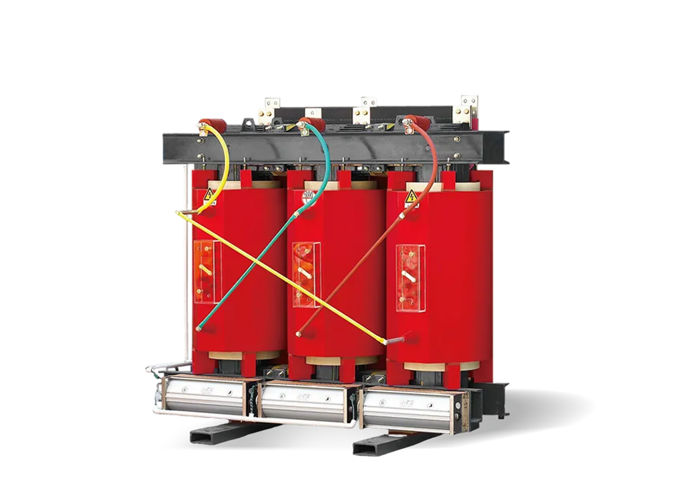
SZ11 Series 35KV oil-immersed transformers are essential power transmission and distribution equipment in medium-voltage power systems, playing a critical role in voltage conversion and power distribution. Their core function is to step down high-voltage electricity (typically from 35KV or higher transmission networks) to the 6-10KV medium-voltage level for safe delivery to industrial plants, commercial complexes, and residential communities, or to step up low-voltage power generated by small-scale power sources (such as industrial self-provided generators) to 6-10KV for grid connection. This voltage regulation process ensures efficient, stable, and safe power supply to end-users while minimizing energy loss during transmission.
|
□ |
□ |
□ |
□ |
□ |
□ |
□ |
|
↓ |
↓ |
↓ |
↓ |
↓ |
↓ |
↓ |
|
Product model |
Loss level |
Special purpose or special structure |
Rated capacity kV.A |
System nominal voltage kV |
Special usage environment |
Energy efficiency level |
| D-Single-phase S-Three-phase F-Air cooling Z-On load voltage regulation |
11 13 14 20 22 |
M-Fully sealed M.RL-Fully sealed three-dimensional coil iron core |
GY-Plateau TA-Tropic TH-Humid tropical zone |
NX3 NX2 NX1 |
The three-phase oil immersed distribution transformer produced by our company adopts a new insulation structure on the body, which improves the ability to withstand short circuits; The iron core is made of high-quality cold-rolled silicon steel sheets; The high-voltage winding is made of high-quality oxygen free copper wire and adopts a multi-layer cylindrical structure; All fasteners are treated with special anti-corrosion measures. Adopting a corrugated oil tank and a fully sealed structure.The product has the characteristics of high efficiency and low loss, which can save a lot of electricity consumption and operating costs. It has significant social benefits and is a high-tech product promoted by the country.
Reliable structure
Our company has made many improvements based on traditional structure and mature technology, such as adopting:
① Spiral coils with longitudinal oil ducts provide better internal heat dissipation;
② Improved the effective support of the coil end face, resulting in stronger resistance to short circuit currents;
③ We have adopted new lifting structures and body positioning structures to ensure greater reliability during long-distance transportation and operation;
④ We also have many unique and reliable structures to serve you;
⑤ Choosing transformers with higher performance levels will have a higher level of technical content.
⑥ The oil tank adopts a fully sealed structure, which isolates the transformer from the atmosphere, prevents and slows down oil degradation and insulation moisture, enhances operational reliability, and eliminates maintenance during normal operation.
High quality materials
All raw materials have undergone quality inspection, and all raw material manufacturers have undergone strict review in accordance with the national standard ISO9000.
① Select oxygen free copper wire with lower resistivity and undergo a series of additional surface treatments to make it smoother, without burrs or sharp corners, resulting in lower load loss and more reliable electrical performance of the transformer.
② Select high-quality silicon steel sheets, and with the improvement of performance level, use silicon steel sheets with lower unit loss to reduce no-load loss of transformers.
③ Using high-quality laminated wood insulation components, it will never crack and will not move even under the action of short-circuit current.
④ Selecting transformer oil that has undergone deep filtration has lower levels of water, gas, and impurities, making transformer operation more reliable
⑤ Select high-quality rubber sealing materials to effectively prevent aging and prevent leakage.
Normal usage conditions
Altitude: Not exceeding 1000m;
Environmental temperature: Maximum temperature+40 ℃; The average temperature of the hottest month is+30 ℃; Maximum annual average temperature+20 ℃; The minimum outdoor temperature is -25 ℃. The waveform of the power supply voltage is approximately a sine waveFor three-phase transformers, the three-phase power supply voltage should be roughly symmetrical
Installation environment: No obvious pollution in the installation environment; Ground acceleration caused by earthquake ag: Horizontal direction below 3m/s², vertical direction below 1.5m/s²
Special usage conditions
Any special usage conditions that need to meet the normal usage conditions of the transformer should be explained during the inquiry and ordering process.
| Rated
capacity kV.A |
Voltage combination kV | Connection
group |
Loss kW | No-load
current % |
Short-
circuit impedance % |
Weight kg | Overall dimensions
(mm) L×W×H |
Gauge
Vertical/ Horizontal |
|||||
| High
voltage |
High
voltage tap range % |
Low
voltage |
No-
load |
Load | Body
weight |
Oil
weight |
Total
weight |
||||||
| 800 | 35 | ±3×2.5 | 6.3 10.5 |
Yd11 | 1.25 | 9.88 | 0.9 | 6.5 | 1735 | 995 | 3625 | 2790×1220×2130 | 820/820 |
| 1000 | 1.50 | 12.16 | 0.9 | 2015 | 1105 | 4055 | 2830×1240×2150 | ||||||
| 1250 | 1.77 | 14.63 | 0.81 | 2190 | 1155 | 4580 | 2870×1310×2210 | ||||||
| 1600 | 2.16 | 17.48 | 0.77 | 2535 | 1295 | 5245 | 2875×1310×2380 | ||||||
| 2000 | 2.30 | 19.20 | 0.50 | 2855 | 1345 | 5935 | 2980×2880×2380 | 1070/1070 | |||||
| 2500 | 2.72 | 20.60 | 0.50 | 3815 | 1575 | 6745 | 3060×2190×2490 | ||||||
| 3150 | 35~
38.5 |
3.23 | 24.70 | 0.50 | 7.0 | 4235 | 1860 | 8780 | 3180×2240×2510 | ||||
| 4000 | 3.87 | 29.10 | 0.50 | 5230 | 2260 | 9820 | 3270×2410×2600 | ||||||
| 5000 | 4.64 | 34.20 | 0.50 | 6195 | 2545 | 11510 | 3490×2480×2840 | ||||||
| 6300 | 5.63 | 36.70 | 0.50 | 8.0 | 8315 | 3095 | 14805 | 3710×2600×3005 | 1475/1475 | ||||
| 8000 | 6.3 6.6 10.5 11 |
YNd11 | 7.87 | 40.60 | 0.40 | 9870 | 3480 | 16590 | 3850×2680×3230 | ||||
| 10000 | 9.28 | 48.00 | 0.40 | 11025 | 4160 | 19930 | 3960×2750×3310 | ||||||
| 12500 | 10.0 | 56.80 | 0.35 | 14270 | 5265 | 24295 | 4035×2980×3530 | ||||||
| 16000 | 13.1 | 70.30 | 0.35 | 17780 | 6280 | 28720 | 4140×3200×3660 | ||||||
| 20000 | 15.5 | 82.70 | 0.30 | 20205 | 7415 | 37380 | 4070×3580×4170 | ||||||
| 25000 | 18.3 | 97.8 | 0.30 | 10.0 | 24950 | 9030 | 43425 | 4710×4120×4310 | 2040/2040 | ||||
| 31500 | 21.8 | 116.00 | 0.30 | 29820 | 11025 | 51555 | 5360×4570×4450 | ||||||
Note: ① For transformers with low voltage of 10.5kV, products with connection group number Dyn11 can be provided.
② The maximum current tap is -7.5% at the tap position.
③ The dimensions provided are only for reference when selecting, and the final dimensions are subject to the product outline drawing.